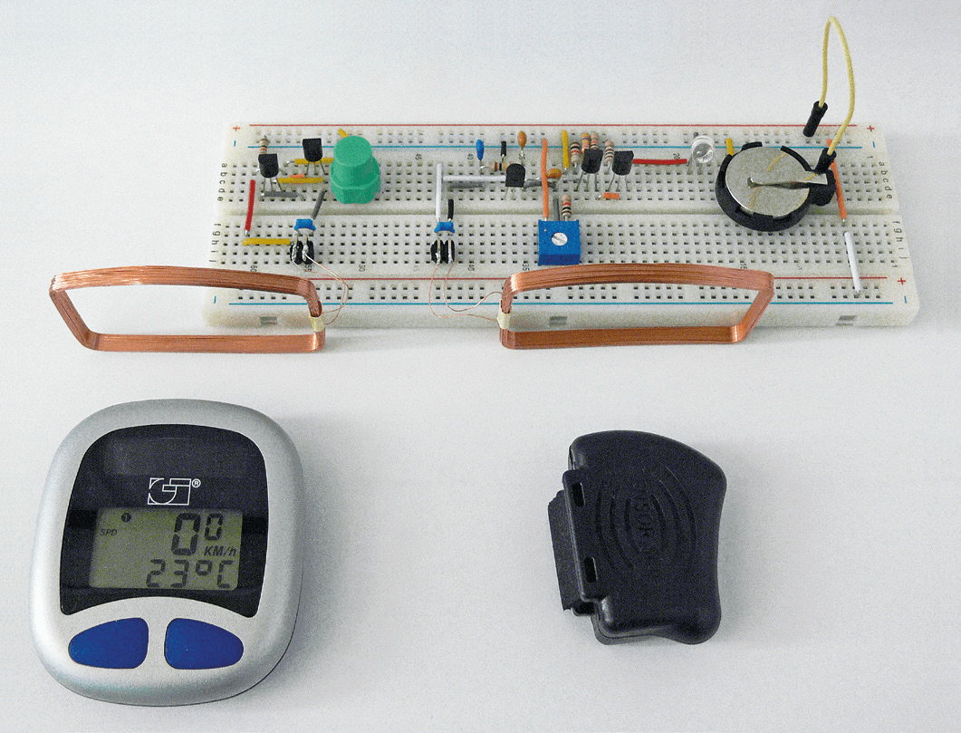
It only took a few minutes to build the transmitter on a prototyping plug board and test it out. The complete circuit of the prototype can be seen in Figure 2. In use, push button S2 can be pressed approximately once per second to simulate the speed of the cycle wheel revolving. The receiving part of the circuit now responded immediately and the red LED flashed in time with the push button action. The piezo buzzer also gave out a click at the same time. Now it was time to move the cycle computer close to the transmitter coil in the test equipment. At a distance of around 20 cm from the coil, the computer began to detect the signal and showed a speed reading corresponding to the rate at which the push button was pressed. That’s a relief, the most expensive part of the cycle computer works correctly and the fault must be in the speed sensor and transmitter. The transmitter in the diagnostic tool has a resonant circuit that can be adjusted by trimmer P2. By connecting a frequency counter at the emitter of T3 it was possible to show that the cycle computer receiver had a relatively wide bandwidth; responding to signals in the range of 105 to 128 kHz.
Figure 2. Thanks to the highly integrated receiver chip the complete circuit fits on a prototyping plug board.
All’s well that ends well
There wasn’t any doubt now; the fault was with the transmitter part of the cycle computer. Further investigation revealed that the magnet had no effect on the reed relay sensor and its contacts had in fact become fused together. It was replaced with a new one and once again the tester was used to check that everything worked correctly. Now when a magnet was passed across the transmitter coil the receiver LED lit up and the buzzer made a click. With the cycle computer refitted to the bike the display showed the correct speed reading. The diagnostic tool had proved its worth; tracking down the fault was a breeze. Finally it is important to note that this circuit is only suitable for the more basic type of bike computer. The more up to date highend digital bike computers operate at a frequency of 433 MHz which is not supported by this design.
Elektor Magazine has been one of the leading sources of information on electronics for engineers, designers, start-ups and companies for 65 years. Our magazine is powered by an active community of electronics engineers – from students to professionals – who are passionate about designing and sharing innovative ideas.
For them, we publish hundreds of items a year, in formats such as articles, videos, webinars, and other learning formats. Our mission is to share knowledge in every possible way and inspire readers with the latest developments within the electrical engineering sector.
Thank you for your vote!
Leave further comments in the fields below.
Thank you for your vote!
If you wish to leave a comment with your rating, please first use the login below. If not, just close this window.

Discussion (0 comments)