
DC Current-Sense Clamp
on
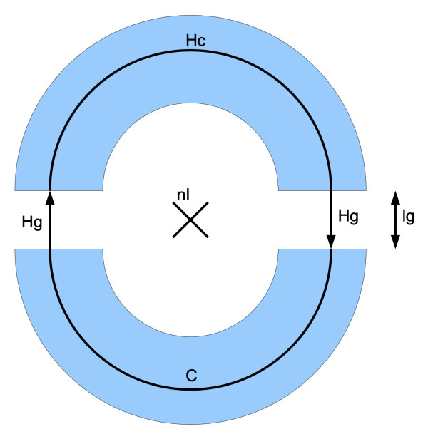
Before we embark on the design of such a project, it’s always a good idea to research the topic and look at any commercial examples already available to see how they are designed and how they can be improved. A current clamp consists basically of two ferrite core halves. The core is composed in such a way that the two halves are separated by an air gap (Figure 1). The current flowing through the wire enclosed by the core has the value nI.
Mathematical Relationships
The value n indicates the turns count (The number of turns that the conductor carrying the current to be measured is wound around the sensing core); it is a multiplication factor applied to the magnetic field measurement which magnetizes the core. The magnetic flux density in the core Bc (where c stands for Core) is the same as in the air gap Bg (where g indicates Gap) so that Bg = Bc. This is a consequence of Maxwell’s equations. For simplicity we can assume that the magnetic fields are homogeneous in the core and the air gap. The material equation Bg = μ0 x Hg applies in the air gap region while in the core Bc = μr x µ0 x Hc. Ferrite materials have a typical permeability value μr of around 2,000. From this Hg = μr x Hc, i.e., in the core, the magnetic excitation is smaller by a factor of μr than in the air gap. In practice, therefore, we can often neglect the core excitation factor.
Ampère’s circuital law relates the integrated magnetic field around a closed loop to the current passing through the loop. The line integral of the magnetic H field around a closed curve equals the free current nI. In Figure 1 the curve is shown as C. The air gap here has the length lg = 1.6 mm and the length of one core-half is given by lc = π x dc / 2 where the core diameter dc = 18 mm. Ampere’s law indicates:
2 x lg x Hg + 2 x lc x Hc = nI
If we insert the value of Hc and solve the equation for Hg, we get:
Hg = nI / (2 x lg + 2 x lc / µr)
This allows us to calculate the magnetic field detected by the sensors as a function of the current. In this project, two A 1324 LUA-T Hall sensors with a sensitivity of S = 5 mV / G are used. This results in a voltage output from the sensors equal to:
V = 2 x S x µ0 x nI / (2 x lg + 2 x lc / µr)
By plugging values into the equation we get:
V = I x 38.92 mV / A
When we consider the levels of current typically encountered for average electronic applications this produces voltages in the millivolt region which are not too extreme. If we ignore the field in the ferrite we can simplify the expression to:
V = S x µ0 x nI / lg
which gives V = I x 39.26 mV / A , giving a simplified scaling factor close enough to the value derived above.
The Ferrite Core
The core element of the DC amp-clamp consists of the two halves of a standard, hinged EMI-suppression ferrite that you often find clamped to cables exiting an enclosure containing electronic equipment (Figure 2).
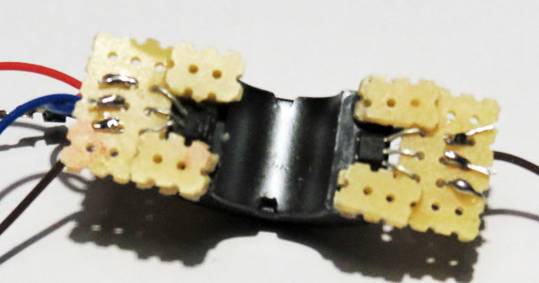
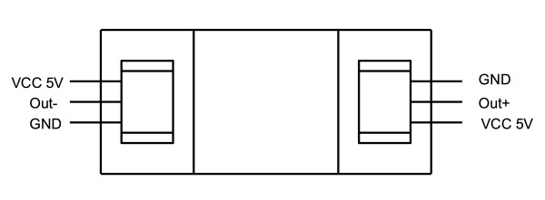
The two Hall sensors are glued to the end cross-section surfaces of one half of the core to form the air gaps. A small piece of 1.6 mm thick pertinax or perf board (with any copper tracks removed) carries the sensor and defines the air gap. In Figure 3 you can see how the sensors are positioned.
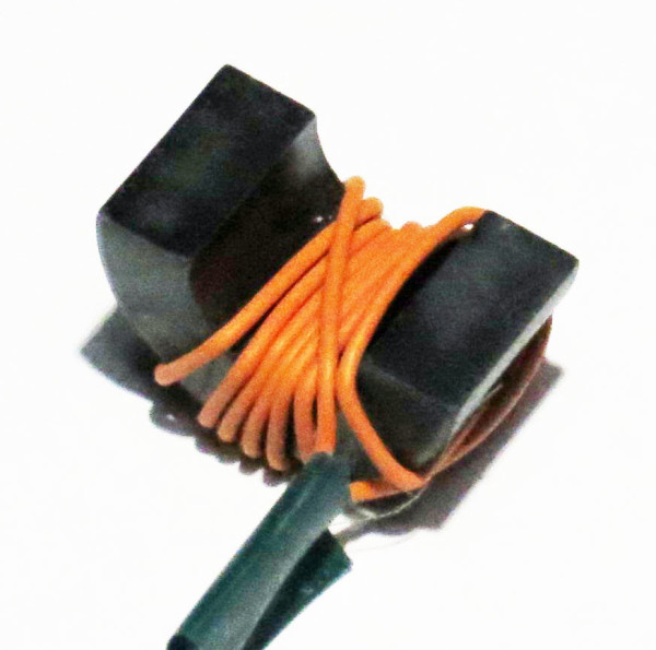
The two core halves can then clamped together using, for example, adhesive tape or a rubber ring. The current-carrying conductor can then be positioned through the centre hole in the ferrite core assembly. Figure 4 shows an example where a single core conductor has been looped several times around the core which has the effect of linearly increasing the sensitivity of the Hall effect sensor.
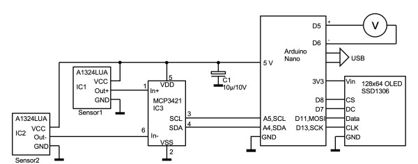
The Electronics
An MCP3421 is used as the analog/digital converter. This device is a low-cost 18-bit converter. It has an internal voltage reference of 2.048 V and uses a differential input stage. The quiescent voltage output level of the Hall sensor is half-rail. When they are positioned in the core air gaps as shown, the magnetic flux produced by the current flowing in the current-carrying cable produces a positive-going voltage change at the output of one sensor and a corresponding negative-going change in the other sensor output. Connected in this way, their output voltage swings are effectively added at the differential input stage of the A/D converter. The resolution of the 18-bit A/D converter is 2.048 V / 217 = 0.015 mV, which is adequate for this application.
An Arduino Nano microcontroller is used as the CPU; it has more than enough GPIO options for our design. A low-cost 128 x 64 pixel OLED display serves as the display. Altogether the relatively simple circuit can be seen in Figure 5. If you would prefer to use an analog indicator, you can also connect a moving-coil voltmeter at the output. One volt output then corresponds to one ampere sense current.
The Commands
To operate and to set the scaling parameters used in the author’s software, a few commands can be entered via the serial interface of the Arduino IDE. The measured values are also displayed via the serial interface.
Command ‘0’ = zero adjust
This command should only be issued when there is no measurement current flowing through the clamp meter sensing core. The software carries out a zero adjustment and stores the value of this offset in non-volatile EEPROM. The Hall sensors have an offset voltage (which drifts with temperature) that needs to be compensated for in order to get accurate measurements.
Command ‘1’ = Scale factor for 1 A
This calibration step is used to find the internal scale factor when a current level nI = 1 A is flowing through the measured cable. The scaling factor is calculated and then stored to EEPROM.
Command ‘5’ = Scale factor for 500 mA
Like Command ‘1’ but here the reference current is set to 0.5 A.
Command ‘u’
When a value following ‘u’ is entered this value will be output and displayed as a voltage. The amp-clamp meter then enters ‘DVM calibration mode’ for a period of time when you can use the ‘+’ and ‘-’ to calibrate the output to the target value.
Command “d ”
Default values of the parameters are written to EEPROM to initialize it for its first start.
Construction
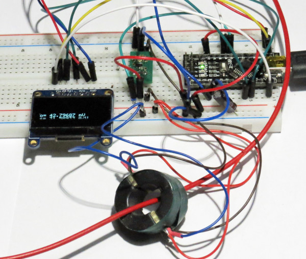
To demonstrate the basic principle, I built the prototype using a prototyping plug board and flying lead wire jumpers to connect the various components used in the circuit (Figure 6). In the foreground, you can see the ferrite core with the small display on the left and the Arduino Nano on the right.
The software was developed using the Arduino IDE and then downloaded to the Nano board. The latest version of this software is available free of charge from the Elektor web page for this article [1]. The prototype Amp-clamp project was tested and behaved as expected when it was fired up. We hope this circuit will inspire you to carry out your own experiments or build other projects relating to the magnetic measurement of currents!
Questions or Comments About the Amp-Clamp?
If you have any questions or comments regarding this article, please let us know. Contact us at editor@elektor.com!
Discussion (8 comments)