
Getting Started With the Zephyr RTOS
on
Zephyr is scalable, making it suitable for a wide range of devices with different resource constraints. Scalability is achieved through a modular architecture that allows developers to include only the components they need, minimizing the system footprint. The Zephyr website claims that it runs on systems from as small as 8 KB of memory up to systems with gigabytes of memory.
Wide Hardware Support
Zephyr supports a broad range of architectures, including ARM, x86, RISC-V, Xtensa, MIPS and more. FPGAs too are supported with Nios2 and MicroBlaze soft cores. At the time of writing, Zephyr lists over 600 usable boards, including the Arduino UNO R4 Minima, GIGA R1 WIFI and Portenta H7, multiple flavors of the ESP32, both versions of the BBC micro:bit, the Raspberry Pi Pico (and even the Raspberry Pi 4B+), nRF51 and nRF52 boards, the NXP MIMXRT1010-EVK and family, and the STM32 Nucleo and Discovery families. While I only listed boards commonly encountered in Elektor, there are many more.
Besides processor boards, Zephyr also has support for many add-on boards (known as “shields”), and it comes with drivers for all sorts of interfaces and more than 150 sensors.
Multitasking, Networking, and Power Management
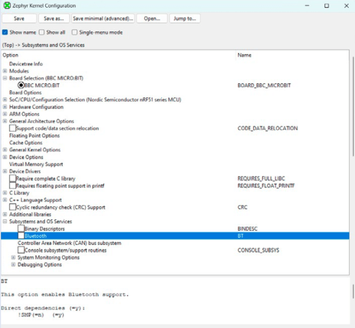
Being a real-time operating system (RTOS), Zephyr provides features such as preemptive multitasking, inter-thread communication, and real-time clock support. The OS also comes with networking technologies and protocols like TCP/IP, Bluetooth, and IEEE 802.15.4 (used in e.g. Zigbee), MQTT, NFS, and LoRaWAN. Together with its networking capabilities, the power management features built into Zephyr make it suited for energy-efficient IoT applications and battery-operated devices.
A set of libraries and middleware simplify common tasks, such as communication protocols, file systems, and device drivers. Know that Zephyr is also designed to be compatible with safety certifications such as ISO 26262, making it suitable for safety-critical applications.
Inspired by Linux
Zephyr is not Linux, but it makes use of concepts, techniques and tools used by Linux. As an example, Kconfig is used for configuring the OS, and hardware properties and configurations are described using the Device Tree Specification (DTS). Therefore, Linux developers will feel quickly at home when coding for Zephyr.
Open Source
Last, but not least, Zephyr is released under the permissive Apache 2.0 license, which allows for both commercial and non-commercial use. Its user community provides support and documentation. You can join too.
Trying Out Zephyr
Trying out Zephyr has been on my to-do list for several years, but my first experiences with it were not very encouraging, so I never dug much deeper. At the time, one of its main issues was (besides getting it to compile without errors) that it required a programming pod to program the target controller, making it less suitable for makers. Thanks to Arduino and its bootloader, we have become used to not needing special programming tools, and so requiring one felt like a step back.
Choosing a Board
Things have evolved since. As mentioned above, today, Zephyr supports over 600 microcontroller boards. Chances are that you already own one or more compatible boards. Looking through the list, I discovered that I have more than a dozen different supported boards at my disposal.
Long Live the BBC micro:bit!
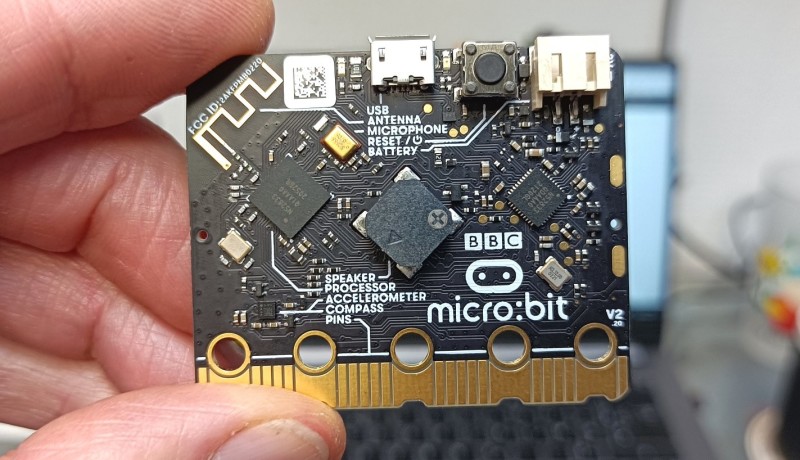
I tried most of them to finally settle on the BBC micro:bit for my experiments (Figure 1, known by Zephyr as bbc_microbit or bbc_microbit_v2, depending on the board’s version). Compared to my other options, besides being readily available, the BBC micro:bit has probably the best Zephyr support, meaning that all of its peripherals are accessible and supported by a few examples. Best of all, it can be programmed and debugged without needing extra tools.
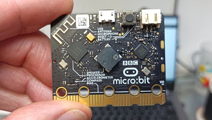
would have thought that this little board intended for teaching programming to 10-year-olds using MakeCode,
a Scratch-like graphical language, would also be a super tool for seasoned embedded software developers
interested in learning an industrial-grade, real-time operating system?
The popular ESP-WROOM-32 (known by Zephyr as esp32_devkitc_wroom) is also a suitable candidate, but debugging requires an external tool. The Arduino GIGA R1 WIFI is another good option, but its bootloader is destroyed when using Zephyr. You can restore it, of course, but it is an unwanted collateral. Officially, the Arduino UNO R4 Minima requires an SWD-capable programming pod (as do many other boards, including the Raspberry Pi Pico), but I did find a way around this using dfu-util (see below). Like the GIGA R1, its Arduino bootloader gets trampled by Zephyr, though.
Use an Emulator Instead
In case you don’t have a suitable board, but you really want to try Zephyr, know that it has built-in emulator support for QEMU (on Linux/macOS only). This lets you run and test applications virtually. Renode from Antmicro is capable of similar feats, although I didn’t try it.
Installing Zephyr
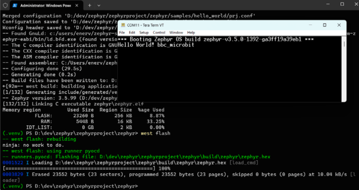
I installed Zephyr on a computer running Windows 11 — I did not try Linux or macOS. Detailed and working installation instructions are available online. The steps to take are clearly pointed out and don’t need further explanation. I used a virtual Python environment, as suggested. This does mean that you must write down the command to activate the virtual environment somewhere, as you will need it every time you start working. If you use Windows PowerShell, you should launch the script activate.ps1; in Command Prompt it is the activate.bat batch file. Windows PowerShell is better at processing compiler and linker ouput (Figure 2).
but it is not a terminal. Windows PowerShell, a.k.a. Terminal, is thus more suitable.
Zephyr consists of two parts — the OS itself and an SDK containing a collection of MCU tool chains (21 at the time of writing…). The OS and the SDK don’t have to be installed in the same place. In total, for me, it consumed about 12 GB of precious hard disk space. To reclaim some space, you can delete tool chains that you don’t need.
After installation, see if it is working by building a sample and uploading it to the board with the command below. Replace <my_board> by the name of your board, e.g., arduino_uno_r4_minima:
west build -p always -b <my_board> samples/basic/blinky
If you don’t want to change the path to the example, you must run this command inside the folder (where (.venv) indicates that you are in a virtual environment):
(.venv) <my_path_to_zephyr>\zephyrproject\zephyr
If the example builds without errors, you can upload it to the board using
west flash
and the board’s “default” LED starts flashing at a rate of 0.5 Hz.
As mentioned before, flashing may require an external programming tool, such as a J-Link adapter or another (JTAG or SWD-capable) programmer (Figure 3) and the driver software for it must be accessible (i.e. in the search path, %PATH% on Windows). If it isn’t, you will be informed about it by a message (often long and cryptic).
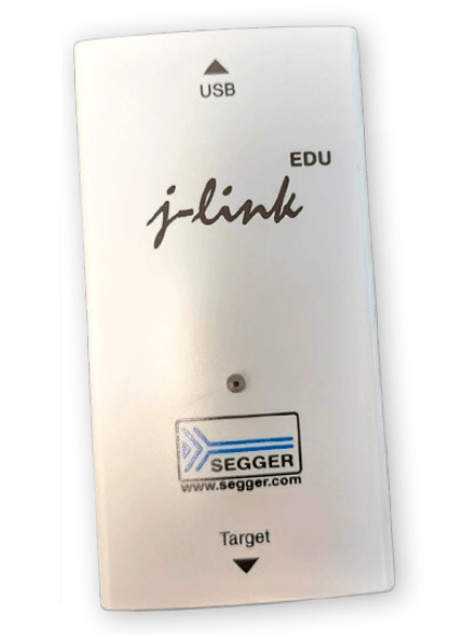
programmer/debug pod is required for your Zephyr experiments
On the BBC micro:bit V2, the first time I had to copy the HEX file manually to the board using the standard micro:bit programming procedure. After that, the flash command worked fine. The executable zephyr.hex is located in zephyrproject\zephyr\build\zephyr\.
The default flash command for the Arduino boards, UNO R4 Minima and GIGA R1 WIFI, requires that the dfu-util programming utility is in the OS’s search path (before you activate the virtual environment, if you use one). This utility is included in the Arduino IDE. However, where exactly it lives on your computer is up to you to find out (by default in %HOMEPATH%\AppData\Local\Arduino15\packages\arduino\tools\dfu-util\<your most recent Arduino version>). The board must also be put in DFU mode. Do that by pressing the reset button twice. When the LED starts “pulsing” or “breathing,” you can flash the program.
Blinky Compatibility
You may have noticed that I suggested the Arduino UNO R4 Minima as board to use for the Blinky example and not the BBC micro:bit that I was so enthusiastic about earlier. The reason is that despite it having 25 LEDs (not counting the power-on indicator), it does not have an LED that is compatible with the Blinky example. The ESP Wroom 32 doesn’t have one either, but the R4 Minima does.
The GIGA R1 is also Blinky-compatible. The MCU on this board has two cores (Cortex-M7 and -M4) and Zephyr lets you choose which one to use by selecting either arduino_giga_r1_m4 or arduino_giga_r1_m7 for the build command. You can show that the cores are indeed independent by flashing the Blinky example twice, once for the -M4 and once for the -M7. The GIGA has an RGB LED and Blinky will use different colors for each core: blue for the M4 and red for the M7. To make the two Blinkies more distinct, you can change the blink rate for one of them (in samples\basic\blinky\src\main.c, change the value of SLEEP_TIME_MS).
Hello World
For boards without a Blinky LED, there is the hello_world example that outputs a string on the serial port.
west build -p always -b <my_board> samples/hello_world
west flash
This example works with both the BBC micro:bit and the ESP-WROOM-32 module. To see the output string, open a serial terminal program on your computer. The data rate is usually 115,200 baud (115200,n,8,1). You may have to reset the board first because the message is printed only once, and you may have missed it (Figure 4).
you will not see the welcome message
On the R4 Minima and the GIGA R1, the serial output is on pin 1 and not, as you naively may expect, on the USB-C port as it would be in the Arduino IDE. This is because the USB port is a peripheral of the MCU and not a separate chip. Since Zephyr is a modular and scalable OS, USB support — like every other module or peripheral — must be explicitly enabled for the project before it can be used. You do this in the project’s configuration files. More on those later.
For boards without a built-in serial-to-USB converter, you must find the serial port (usually port 0 in case the MCU has more than one) and connect it to your computer through an external serial-to-USB converter.
Pushing It a Bit Further
If you managed to get both the Blinky and hello_world examples to work on your board, you are in a pretty good position to create a working application running on Zephyr. If only one works, and you would like the other to work too, things are a bit more complicated.
I selected the BBC micro:bit as my preferred board for Zephyr experiments, even though it isn’t compatible with the Blinky example. That’s not really a problem, however, as the board comes with a few examples (in the bbc_microbit subfolder of the samples\boards\ folder), one of which (display) is much nicer than a single-LED Blinky. There are also examples for other boards, but for very few compared to the 600+ supported boards (not even 5%). Furthermore, most of these examples concern advanced or obscure use cases.
When you try to build Blinky for the BBC micro:bit (or the ESP-WROOM-32 or any other incompatible board), you will end up with an incomprehensible error message. What it tries to tell you is that led0 is an unknown entity. This is the default Blinky LED (a bit like LED_BUILTIN on Arduino). As the micro:bit has an extension port to which you can connect LEDs and stuff, let’s attempt to define one of these port pins as led0.
Before we do so, make a back-up copy of the samples/basic/blinky folder or create a copy with a new name and use that instead. In what follows, samples/basic/blinky is used.
The Device Tree
Defining an led0 takes us to the device tree, already briefly mentioned. The device tree, contained in one or more text files, lists the peripherals and memory available on a board or in a controller. In Zephyr, these files have the .dts or .dtsi (“I” for “include”) and files may include other files. Processor .dtsi files are in the dts folder, board .dts and .dtsi files are in the boards folder. Both folders are organized by processor architecture.
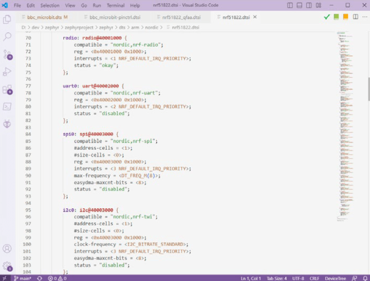
To view DTS(I) files in a somewhat more comfortable way, you can use the DeviceTree plugin for Visual Studio Code. This plugin provides syntax highlighting and code folding, making the files easier to read (DTS files use C language-style syntax). Figure 5 shows an extract of the .dtsi file for the nRF51822 that is at the heart of the BBC micro:bit V1 board. This file is included by the board’s DTS file. As an example, note how the status of uart0 is set to "disabled". This status is overridden in the board’s DTS file, where it is set to "okay", meaning that it may be used. The same is true for gpio0 and i2c0.
I²C in the Device Tree
Another snippet of the .dts file for the BBC micro:bit is visible in Figure 6. It shows the device tree for the I²C bus. The micro:bit has one or two sensors attached to the bus (depending on the micro:bit V1 board variant) and they are represented in the tree by mma8653fc and lsm303agr (the latter comprises two sensors, which is why it appears twice in the tree). The first one has status "okay", while the other two are "disabled". This is correct for my board variant, which is a sample from the very first micro:bit V1 generation.
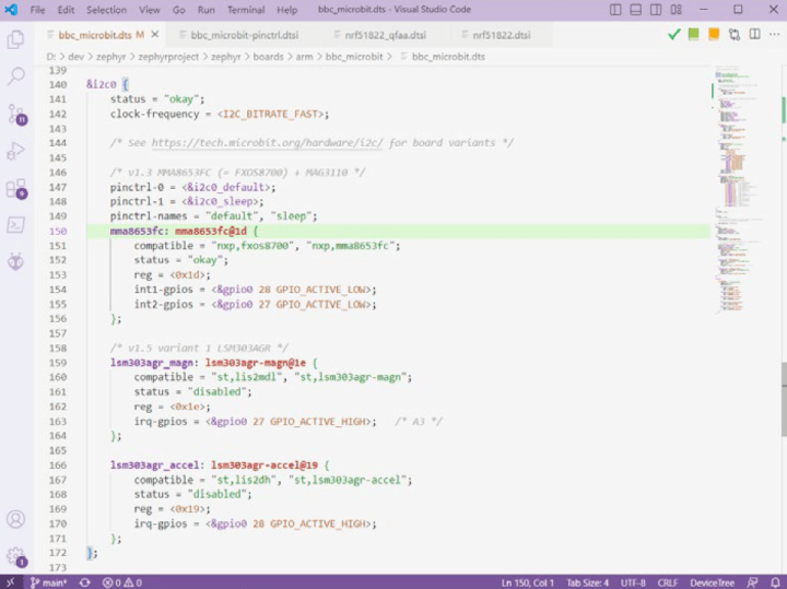
Taken from the bbc_microbit.dts file
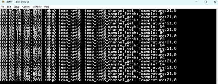
As the snippet shows, this sensor is compatible with the FXOS8700 and MMA8653FC, its address on the I²C bus is 0x1d, and two int (interrupt) signals are declared that are connected to two GPIO pins: 27 and 28. If you want to try it, a demo program is available:
west build -p always -b bbc_microbit samples/sensor/fxos8700
west flash
Note that this won’t work for the BBC micro:bit V2, as it has a different sensor in its device tree. The output of the demo is shown in Figure 7, but we are digressing.
Overlaying the Device Tree
Back to our LED, led0. The board’s device tree does, as expected, not mention led0, so we must add it. We could insert it directly into the board’s device tree file, but that would be incorrect as the board does not have an led0. The proper way to extend a device tree is by adding an overlay for it. The contents of an overlay file are added to the device tree. Sections that exist in the tree are extended (in case of a new item) or overwritten (in case the item already exists in the tree); new sections are added.
Overlays must be placed inside the project folder, in a subfolder named boards. When this subfolder is present, the build process will search it for a file with the name <my_board>.overlay. In my case, the filename is bbc_microbit.overlay (bbc_microbit_v2.overlay for V2 users) Figure 8 shows the contents of the file.
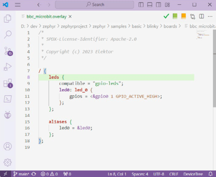
Add a Blinky LED
Zephyr has a special device tree keyword for LEDs, which is leds, so we create a node (branch) for it (you can call it whatever you want, but stick to leds if it is supposed to be overlayed on an existing leds node). This node is to be added to the root of the device tree; therefore a forward slash ‘/’ is placed in front of it as that means root in DT language. The next line states that this branch is compatible with the gpio-leds driver built into Zephyr (you can find the interface for this driver in zephyr\include\zephyr\drivers\led.h).
Child Nodes
Next comes a list of LED child nodes. Since I have only one LED, there is only one child node, led_0, which I labeled led0. Labeling a node is optional, but it allows referencing the node elsewhere in the tree, which we will do a few lines further down. Also, they can be used by the application (developer) to get access to nodes and their properties.
A child node must specify the properties of the device. In the case of an LED, only the GPIO pin is a required property, but the optional property named label may be added. Such labels can be used for providing documentation or human-readable information to the application. They have no other use.
As GPIO pin, I chose 1, which corresponds to the large hole/pad 2 on the micro:bit extension connector. If you have a BBC micro:bit V2, use 4 as GPIO pin (instead of 1).
Create an Alias
The next step is needed because the Blinky example expects it. It consists of creating the led0 alias for our LED. You might think that labeling the child node would have been enough, but it isn’t, because Blinky uses the DT_ALIAS macro to get access to the LED child node. Therefore, we must provide something that this macro can digest, which happens to be an alias. It goes inside the aliases block. If Blinky had used the DT_NODELABEL macro instead, then an alias would have been superfluous, as DT_NODELABEL grabs the led0 child node label directly. I know, having labels and aliases with the same name is a bit confusing, but it is required for my explanation.
Zephyr Macros
Even though macros are frowned upon in C/C++ programming, Zephyr uses them a lot. Macros such as DT_ALIAS and DT_NODELABEL allow the application and project configuration tools to extract information from the device tree, and they are plentiful. You can find their descriptions in the Zephyr manual, in the chapter, “Devicetree API”.
Fun fact: Many (all?) Zephyr macros expect their arguments to be lowercase, with the characters that are not letters (‘a’ to ‘z’) or numbers (‘0’ to ‘9’) replaced by underscores (‘_’). This is called lowercase-and-underscores compatible. As an example, imagine I had labeled the LED child node from before LED-0 instead of led0. Then, the argument to use with DT_NODELABEL would have been led_0, i.e. DT_NODELABEL(led_0) because ‘-’ is not a letter or a number, and letters must be lowercase. In other words, to the application developer using device tree macros, the underscore character is a wildcard. Thus, led_0 in the application can refer to either led_0, led-0, Led_0, LED-0 and ledé0 (and every other variation you can come up with) in the device tree. With this in mind, it is highly recommended to carefully read the documentation of Zephyr macros.
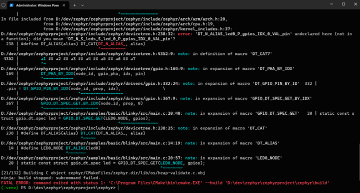
Thou Shalt Not Make Mistakes
Note that making mistakes in the device tree is punished by the compiler shouting “FATAL ERROR” at you without providing any further information.
Pristine Builds
When playing around with the device tree or your application, you will likely rebuild your project a lot. To speed things up a bit, remove the -p always (“p” from “pristine”) from the build command. This stops it from rebuilding everything from scratch. If, on the other hand, you are trying out many different examples one after the other, then keep it, as it will save you an annoying error about the build folder not being intended for your project.
Note that the flash command also triggers the last build command, so it is enough to just run the flash command every time you change something.
Use a Device Driver
The Blinky example calls the gpio_pin_toggle_dt() to toggle the state of the LED. This is a function of the GPIO driver. Of course, this is perfectly fine, but Zephyr also includes a collection of LED drivers. Using an LED driver not only makes the program more readable, but it also makes the program more flexible and portable, as the LED driver can be replaced by another one without changing the application itself. This is where the scalability and modularity of Zephyr come in.
Kconfig Has a GUI
Integrating an LED device driver in our program requires a few steps. First, the project must be reconfigured so that it will include the driver. The project configuration is handled by Kconfig, the kernel build-time configuration system also used by Linux. There are several ways to interact with it, and one of them is a graphical user interface (GUI). In Zephyr, you open it like this:
west build -t guiconfig
The GUI takes a while to open, but when it does, it looks like Figure 9. It shows a lot of information about the project under development. Note the project-under-development part. To ensure that Kconfig is indeed working on your project, do a pristine build (with the -p always flag) of your project before launching the Kconfig GUI.
So Many Configuration Options…
Take some time to explore the configuration tree. Unfold branches by clicking on the + symbols. Highlight options by clicking on them. This will display some information in the bottom pane. Note how floating-point support for printf() is a configuration option, as is C++ language support. Similarly, under Build and Link Features, you can find compiler optimization options.
There are tons of configuration options. The one that is of interest to us is in the Device Drivers branch. Unfold it and scroll down while looking at all that is available. The LED driver is about halfway down: Light-Emitting Diode (LED) Drivers. Check the checkbox. Leave the options in its subbranch on their default values (Figure 10). Click the Save button and note the configuration file’s path printed at the bottom of the window. It is instructive to inspect this file, just to see what it contains (a lot). Close the GUI.
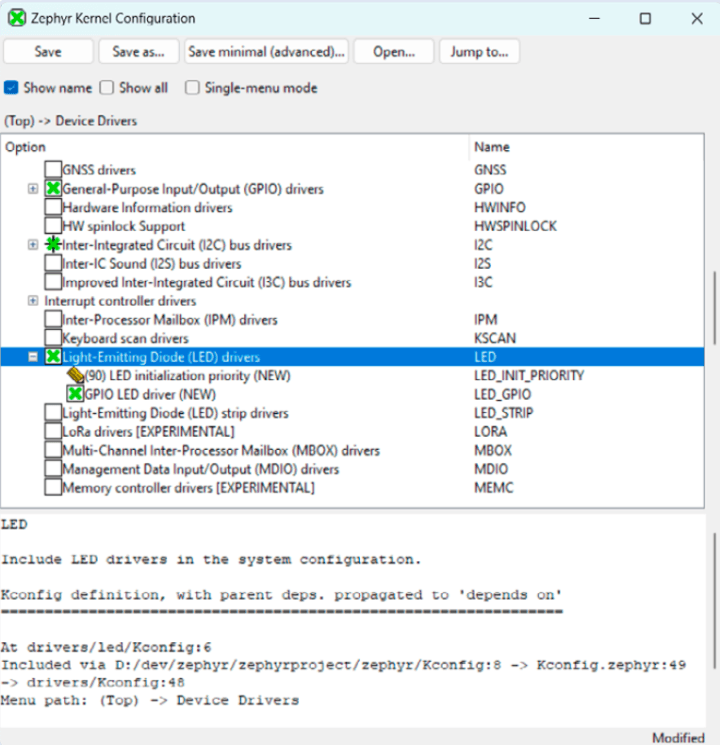
From this point on, do not specify the -p always flag anymore in build commands, as it will undo the changes you made above. I will show later how to make the configuration change permanent.
Blinky With LED Device Driver
Now we can write the new Blinky program — see Figure 11. It starts by including the device and LED driver header files. Then, in the main, we employ the DEVICE_DT_GET_ANY macro to obtain a device reference for the LED from the device tree. Note how the macro’s gpio_leds argument is lowercase- and underscore-compatible, so it will match with the gpio-leds value of the compatible property of the leds node in the device tree (as explained above). If it can’t find one because you made a typo or something, the new Blinky will print the message, “No device with compatible gpio-leds found.” This message will also be triggered when the status property of a device is set to "disabled".
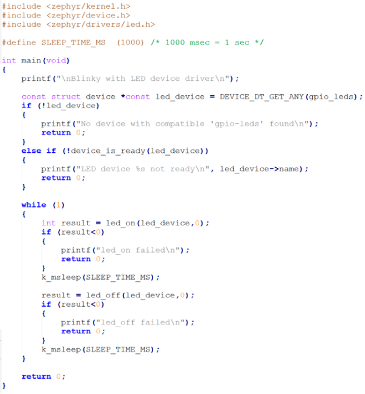
This program should run on any board that has a gpio_leds (or gpio-leds) driver listed in its device tree.
The use in Zephyr of the word “compatible” as a noun takes a bit of getting used to. Therefore, the error message above does not mean that there is no compatible device, but that there is no device having a property named compatible with the value gpio-leds (nor, for that matter, with gpio_leds, remember that the underscore ‘_’ replaces any character except for ‘a’ to ‘z’ and ’0’ to ’9’).
A second check verifies that the device initialized properly. Assuming that it did, we continue.
In the infinite while() loop, the LED is toggled on and off using the led_on and led_off commands provided by the driver. The argument 0 signifies the first (and only) device found by the macro DEVICE_DT_GET_ANY, which is led0.
Check Return Values
As we are using a device driver instead of directly toggling a GPIO pin on the hardware register level, it is good practice to check the return values of all the driver function calls, as they may fail for some reason. A driver must provide certain functions and callbacks, but it can also have optional features. An LED driver, for instance, must implement led_on and led_off, but led_blink is optional. If you call led_blink in our project, nothing will happen because it is not implemented. It exists, but it is empty. The return value will show you this. In general, it is good programming practice to check the return value of every function call.
Build and upload the program like this (note the absence of the -p always flag).
west build -b bbc_microbit samples/basic/blinky
west flash
Configure the Project
If the LED started blinking at 0.5 Hz, we have a working program. To keep it that way, we must make the current configuration permanent. To accomplish this, open the prj.conf file in the folder of our Blinky and add the line (unlike device tree files that use C-language syntax, Kconfig configuration files use Python-language syntax):
CONFIG_LED=y
To check that it works, execute a pristine build of your project, and upload the executable to the board.
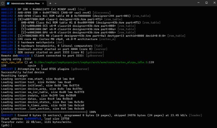
Debugging
If your board allows it (as the BBC micro:bit does) or you have a suitable debugging tool, you can debug the application with
west debug
This will start a gdb server and open a terminal (Figure 12). Consult the internet for learning how to work with gdb as that is outside the scope of this article.
Zephyr Versus Arduino
Now that you have seen how to get started with the Zephyr OS, you may wonder why you would use it. Isn’t it much easier to use Arduino? Like Zephyr, Arduino supports multiple processor architectures and hundreds of boards. Thousands of drivers and libraries have been written for Arduino. If an application or library uses the Arduino Core API, it can be ported easily to any other supported platform with similar peripherals, just like a Zephyr application. Both are open source. So?
Well, Zephyr is intended as an industry-grade, robust RTOS with features such as task scheduling, memory management, and device drivers. Furthermore, Zephyr is designed to accommodate a wide range of project complexities, from small IoT devices to complex embedded systems. It provides greater flexibility, but requires a more profound understanding of embedded development.
Arduino, while offering some real-time capabilities, is not an RTOS but a framework for single-threaded applications with a focus on simplicity and ease of use. Arduino abstracts many low-level details, making it accessible to beginners. However, it can be used on top of an RTOS such as Mbed OS for more complex applications. Work to make the Arduino Core API run on Zephyr is in progress.
It is up to you to decide whether you need Zephyr for your next project or not. You could at least give it a try, as it looks great on any embedded developer’s resume.
Further Reading About Zephyr
That’s it for now. As you will have seen, the Zephyr OS is complicated and has a somewhat steep learning curve. In this article, I have tried to make the ascension a bit easier. However, there is much, much more to say and learn about Zephyr, so don’t think now that you know it all. Refer to this white paper and this article for links to two topics in which you might be interested.
Questions About Zephyr?
Do you have technical questions or comments about his article? Email the author at clemens.valens@elektor.com or contact Elektor.
This article (230713-01) appears in Elektor March/April 2024.
Discussion (1 comment)