
Hands On the Parallax Propeller 2 (Part 3): Blink an LED
on
In the previous articles in this series, we started coding the Propeller 2 MCU and we illuminated an LED using SPIN2. Now I will provide you with a solution to make it blink, and then I will continue with the IO pins. Let’s get started.
A simple solution
You can follow a simple ”turning it off and on again”-scheme. To do so, you need to following ingredients:
- pinwrite()
- repeat()
- waitms()
The necessary steps include:
- Turn the LED on
- Wait 500ms
- Turn the LED off
- Wait 500ms
- Repeat
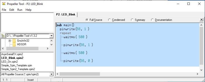
The code will look like what you see in Figure 1. You can download it from the article webpage [1].
After we have used pins as output, the next step would be to show how to use them as inputs. We are not going to so at this point. We will come to this topic, inputs, later. Having a kind of serial data output to talk to a PC makes showing what status we have read from an I/O pin a lot nicer than just blinking an LED. Furthermore, we can use this output to send status data and do some debugging of the code. The next stop in this series will be the smart pins.
Smart pins
These days, marketing teams like to call products “smart” (e.g., “smart city,” “smart data,” and “smart contracts”). With the smart pins, it is a different story, as they can be far more than just ordinary general-purpose IO pins. On other MCUs, you will sometimes have the ability to select from multiple functions for one pin. Some MCUs have, like the ESP32, an IO matrix that can route any internal IO signal form peripherals to any pin. In these cases an IO pin will still be just an IO pin, the functions of — for example — UART, SPI or ADC, will reside inside a dedicated block of hardware that is just connected to the pin itself. With the Smart Pins on the Propeller 2, this changes as the dedicated peripherals are no longer dedicated function blocks inside the MCU that are routed through a IO matrix but integrated, at least partially, into every IO pin. Hence the term smart pin.
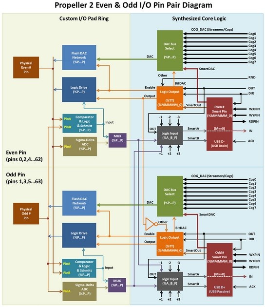
Thankfully the user 'rayman' on the Parallax Forum [2] did a great job by providing the community with an overview of the smart pin internals. You can find his post abou the Propeller 2 and the image at [3] or you can also have a look at Figure 2.
In the “Overview of Smart Pin Functions” section, I include an extract from the Propeller 2 datasheet. You can see that one pin can serve for many functions. Currently, we are only interested in 11110* = async serial transmit to send out data for later debugging purposes. The first step is to figure out how to set the appropriate mode for the pin and if it can be done with pure SPIN2 or if we need to mix in a bit of Assembly language.
UART Configuration
This is the point where you start scratching your head if you are working with SPIN2 and the Propeller 2 for the first time. The current datasheet is, more or less, complete. But reading and understanding everything properly can take longer than expected. Our goal is a simple function, a tx(), that will take a character to transmit to a pin working as a UART. We will work with 115200 baud, 8 data bits, no parity and only one stop bit. The first thing to do is set up the pin.
You must do the following:
- Set up the pin in async serial transmit
- Set the baud rate and data bits
- Enable Smart Pin
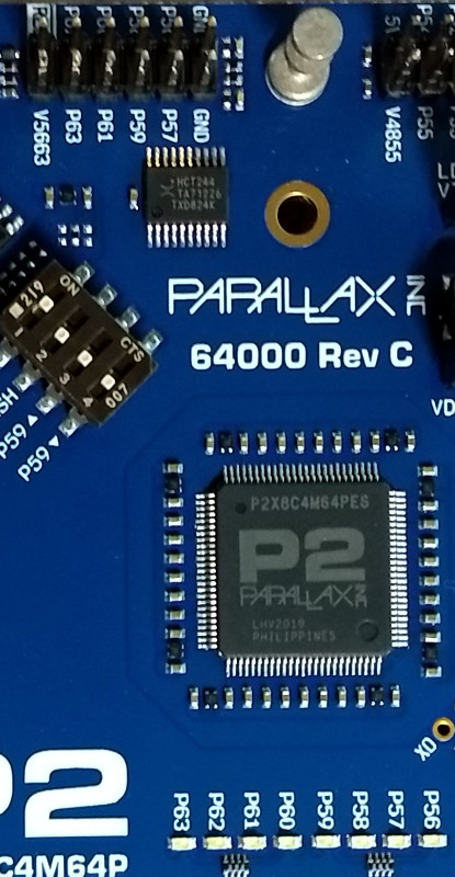
These three simple steps will enable one pin to be a transmitting UART pin. As we will later modify the code and reuse it, we put it into a function. A function simply contains code or code fragments that are used often inside a program. This avoids a copy and paste through the code and also allows maintenance to be done at one place. We will use a function and call it serial_start. This one will take no arguments and simplify to the three steps given above. The pin we use is currently hardcoded to be pin 57 (one of the LED pins also accessible at one of the edge connectors as seen in Figure 3).
Here the function starts with a PUB followed by the name of it. At the end you have a empty braces, showing that we take no arguments.
PUB serial_start()
WRPIN( 57, %01_11110_0 ) 'set async tx mode for txpin
WXPIN( 57, ((217<<16) + (8-1 )) ) 'set baud rate to sysclock/115200 and word size to 8 bits
org 'start of assembly part
dirh #57
end ' end of assembly part
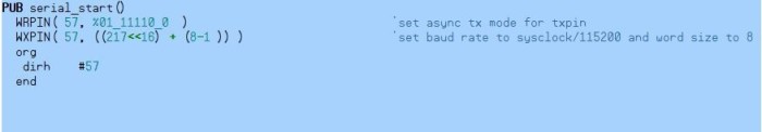
Starting with line 1, you have, as I◦mentioned above, the function — more precisely, the function head. The next line will set the pin 57 into async serial transmit, notable at the 11110. The first bit is always zero; the two most significant bits shown here as ‘01’ denote that the pin shall be driven by the GPIO or Smart Pin function. We use here the SPIN2 WRPIN function to achieve our step one. The next function WXPIN writes, for a smart pin in async serial mode, the desired clock divider and data bits to be used. For simplicity we skip the part with the fraction baud rate divider for now. The value for the baud rate can be calculated by systemclock/baudrate — here 25 MHz/115200 baud — resulting in about 217. This result needs to be shifted by 16 to the right. For the number of bits to transfer, we use the formula (desired bits-1) and this leaves us with (8-1) bits.
This is all the magic needed to set up the transmission speed and data bits. The next three lines look different than the previous code. As this is showing a small assembly section, it may require few words of additional explanation. With org you can start a section of assembly instructions, and they are currently needed here. The assembly command dirh will enable the smart pin functions, as we need to do for our step three. What’s different is now how you tell what pin number we are working on, as this needs to be started with a ‘#’.
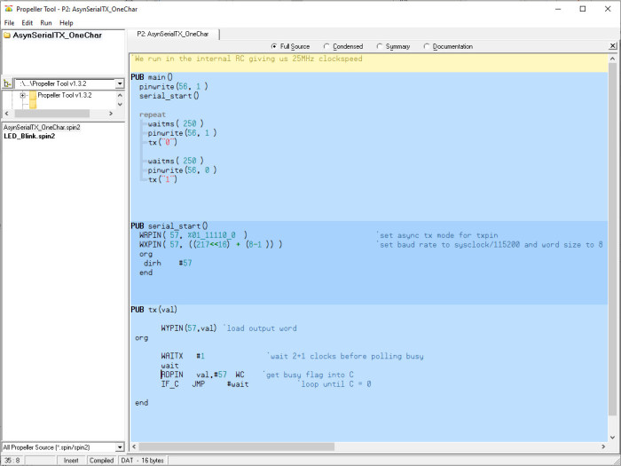
The last line end will end the assembly section. It also at the same acts in this special case as the end of the function itself. It would been great to avoid assembly but currently there is no SPIN2 equivalent for the dirh assembly instruction. The formatted and highlighted code can be seen in Figure 4.
Now that the pin is in the correct mode, we can continue and set up a function, one that sends a character and waits until it’s done. The function can be mostly grabbed from the datasheet [4], page 91. We have seen how to build functions that have no arguments, meaning nothing passed on to them. To send a character, it would be beneficial if we can pass what we like to transmit to the function. As we currently try to avoid as much assembler as possible, we will, where possible, use the SPIN2 functions instead of inline assembly.
Transmission
For transmission, we create a tx function that looks almost identical to our serial_start() function, as you can see at Figure 5.
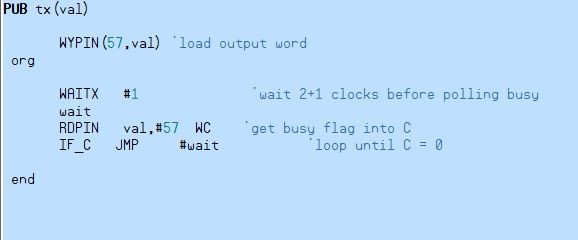
The visible difference, besides the name, is the argument ‘val’ inside the brackets. ‘val’ will carry the character to be printed. Inside the function, we will first write the value into the transmission register of pin 57 using the WYPIN command. The following section consists again of a few lines assembly code. We need to wait until the busy flag for the transmitter is no longer set and the transmission is done. According to the datasheet, we must first wait three CPU cycles to read the flag in a consistent manner. This is achieved by the waitx instruction with the #1 parameter, as its execution takes two cycles + the amount specified for the function (here one cycle). The next line is a label called wait, in assembly language, a place where we later can jump to. RDPIN in assembly, as written here, reads the pin status with carry. This is denoted by the WC at the end of the statement. The carry bit, here serving as busy flag, is important as it denotes if the transmission has been completed.
RDPIN val, #57 WC reads the status including the carry bit into our val value. As the content is currently transmitted, we can repurpose the memory of val to read the smart pin status to it. The last command IF_C◦JMP◦#wait is a conditional jump; in basic it would be the infamous GOTO equivalent combined with an IF statement. Shortly translated it means: Have you read something with the carry bit (here busy flag) set? Go back to the wait label and start from there again, or else move on. Our transmission is done if the carry bit is no longer set, and therefore the function will run to its end and return to where it was called.
Assemble all parts
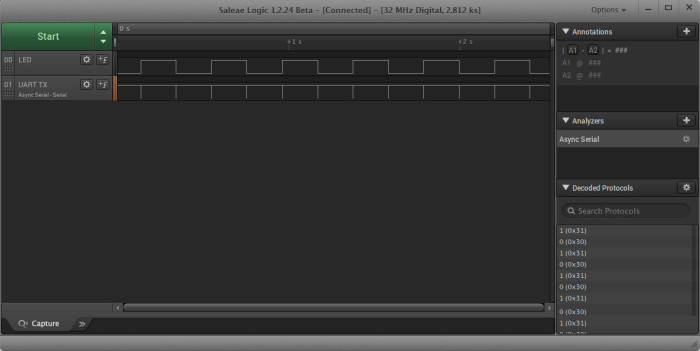
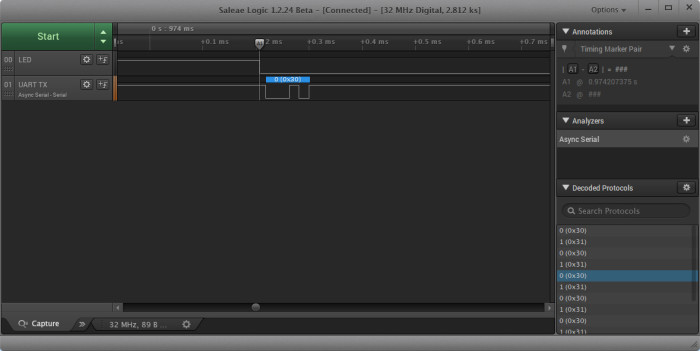
We can now assemble the code and insert after every pinwrite() to transmit a “0” or “1” by using tx(“0”) or tx(“1”) in our code, as shown in Figure 6.
To grab the output attach a USB serial converter. For this purpose, we grabbed our trusty Logic 16 and recorded the output of the LED and the serial transmission and show the result in Figure 7 and Figure 8.
But how about strings? Would it be nice to just do a print(“Hello World”) and have that transmitted over serial like we can do in the Arduino world? Yes, this can be done and we will. The next step in our series about the Propeller 2 will be an introduction on this.
Propeller 2: Overview of smart pin functions:
00000= smart pin off (default)
00001= long repository(P[12:10] != %101)
00010= long repository(P[12:10] != %101)
00011= long repository(P[12:10] != %101)
00001= DAC noise(P[12:10]= %101)
00010= DAC 16-bit dither, noise(P[12:10]= %101)
00011= DAC 16-bit dither, PWM(P[12:10]= %101)
00100*= pulse/cycle output
00101*= transition output
00110*= NCO frequency
00111*= NCO duty
01000*= PWM triangle
01001*= PWM sawtooth
01010*= PWM switch-mode power supply, V and I feedback
01011= periodic/continuous: A-B quadrature encoder
01100= periodic/continuous: inc on A-rise & B-high
01101= periodic/continuous: inc on A-rise & B-high / dec on A-rise & B-low
01110= periodic/continuous: inc on A-rise {/ dec on B-rise}
01111= periodic/continuous: inc on A-high {/ dec on B-high}
10000= time A-states
10001= time A-highs
10010= time X A-highs/rises/edges -or- timeout on X A-high/rise/edge
10011= for X periods, count time
10100= for X periods, count states
10101= for periods in X+ clocks, count time
10110= for periods in X+ clocks, count states
10111= for periods in X+ clocks, count periods
11000= ADC sample/filter/capture, internally clocked
11001= ADC sample/filter/capture, externally clocked
11010= ADC scope with trigger
11011*= USB host/device(even/odd pin pair = DM/DP)
11100*= sync serial transmit(A-data, B-clock)
11101= sync serial receive(A-data, B-clock)
11110*= async serial transmit(baudrate)
11111= async serial receive(baudrate)
* OUT signal overridden
More on Propeller 2 and Related Topics
Want to learn more about topics like Parallax's Propeller 2? Take out an Elektor membership today and never miss an article, project, or tutorial.
Discussion (0 comments)