
Hands On the Parallax Propeller 2 (Part 5): Smart Pin Function
on
Propeller 2 GPIOs
As the Propeller 2’s pins have more than the common functions found in other MCUs, a closer look may reveal some interesting insights. To get a kind of reference, we will first have a look into the GPIO structure of a Microchip Technology ATmega328P. Then, we will go to the Propeller 2 to see if there are differences and how they may come handy later. In the end, it should be easy to read a few button states.
How I/O Pins Work on Other MCUs
Those who are familiar with the ATmega328P will know that we have basically four I/O pin states: being an input, input with pullup, output driving low and output driving high. Analog functions are a specialty of only a few pins on the ATmega328P and will not be covered here. From the datasheet, we can see in Figure 1 how an I/O pin is basically constructed.
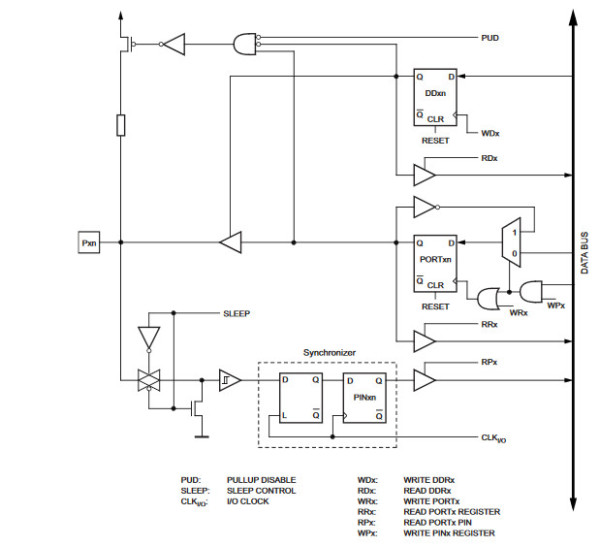
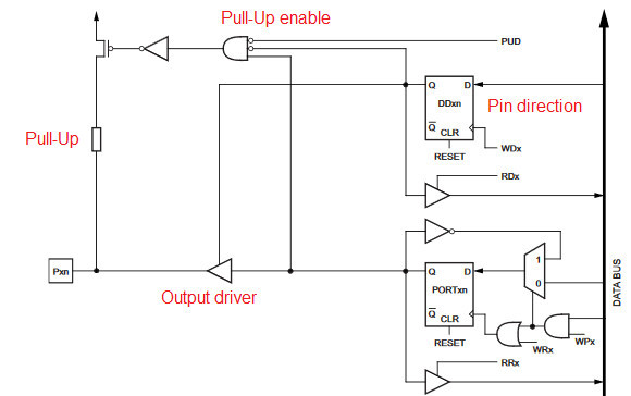
Added in red are some sections of interest. We basically get a control mechanism for a pull-up resistor, that is specified to be 20 kΩ up to 50 kΩ, consisting of a FET and the resistor itself and control logic to enable the FET (as the part in Figure 2 shows).
In the lower section of Figure 1, you can see a transmission gate (Figure 3) that will act as digital controlled switch allowing analog voltages to pass.
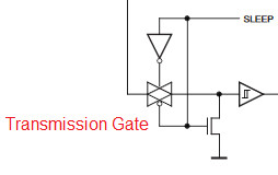
What’s interesting is the SLEEP signal, as this will disable the transmission gate and also at the same time tie its output with a dedicated FET to ground. The reason for this is the Schmitt-trigger, located at the transmission gates output. It is used to transform an analog voltage level into a binary value of zero or one. In the center of Figure 4 is the output stage with enable.
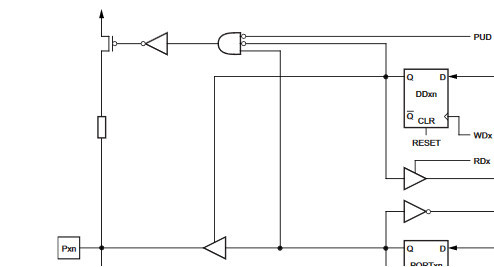
If enable is not asserted, the output stage will be disconnected, or else it will drive a low or high, depending on the applied input. A lot of text for just on and off, but this will show the basics and the pullup will become handy for one reason. We can only globally set all pins at once to sleep (as other parts of the ATmega328). If we like to have one pin unused and do nothing, its input will float. This means that it picks up random noise and the Schmitt-trigger will convert it to a binary zero or one. As the input is random the Schmitt-trigger and internal logic will fast switch between zero and one, meaning that with every transition we need a bit of energy. For an unused pin, this is not desirable and wasting energy. Especially if we run the device with battery power, it is something we have to avoid. Therefore, using the pull-up will set the voltage at the input to VCC and a random switching of the input will not take place. This is a long introduction to something simple that only switches on and off, but now we will focus on the Propeller 2 implementation.
Smart Pins on the Propeller 2
As I mentioned before, there are no simple I/O pins on the Propeller 2. When it comes to the basic input and output functions, a look in the Propeller 2’s preliminary datasheet reveals that we have more than four choices even for the simple input and output configuration. All pins can act in digital or analog input or output modes. We begin with the digital one. Starting with the input, as you may remember from the ATmega328, everything was straightforward, a transmission gate and a Schmitt-trigger to read the signal. This time we have a bit more smarts inside the pin. Figure 5 shows the digital input path, or better paths, for one single pin we have.
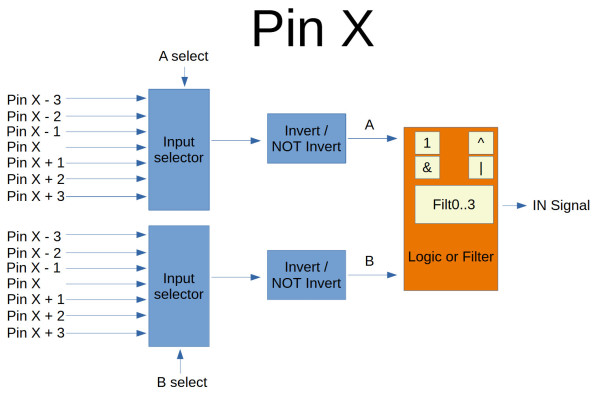
The first thing that is strange is that we have two input selectors to choose from. That allows the current pin and +/- three pins next to it to be selected for each of this inputs. After this selection, we can use the inverted or non-inverted signal, resulting in an A or B term. Our A and B will than be feed into a second part where logic operations or filtering can be performed. The final selected result will be presented as IN signal to the system. This makes the standard pins a bit more complicated but also a bit more versatile than those on an ATmega328P. For the digital output, things are simple: we just have low and high output, nothing fancy here at first sight.
Do you remember the pull-up resistor that we talked at the beginning? The Propeller 2 has more than just one and can also do pull-up and pull-down. The combinations are quite simple:
- 1.5 kΩ
- 15 kΩ
- 150 kΩ
- 19 Ω
- 1 mA
- 100 µA
- 10 µA
- Float
As we can choose to have pull-up or pull-down resistors or current sources, this makes the pins very flexible even for the various busses we may need or like to interact with.
The pull-ups or pull-downs are not done as in the ATmega328 with a sperate FET switching them on or off; instead, these resistors act as drive strength, like they are between the driving stage and the pin output. To use the pull-up or pull-down you switch the pin to be an output with the given resistance and use low or high for pull-up or pull-down. But there is a bit more to the story here, as you can see in Figure 6, which provides insight into the low level design of a pin.
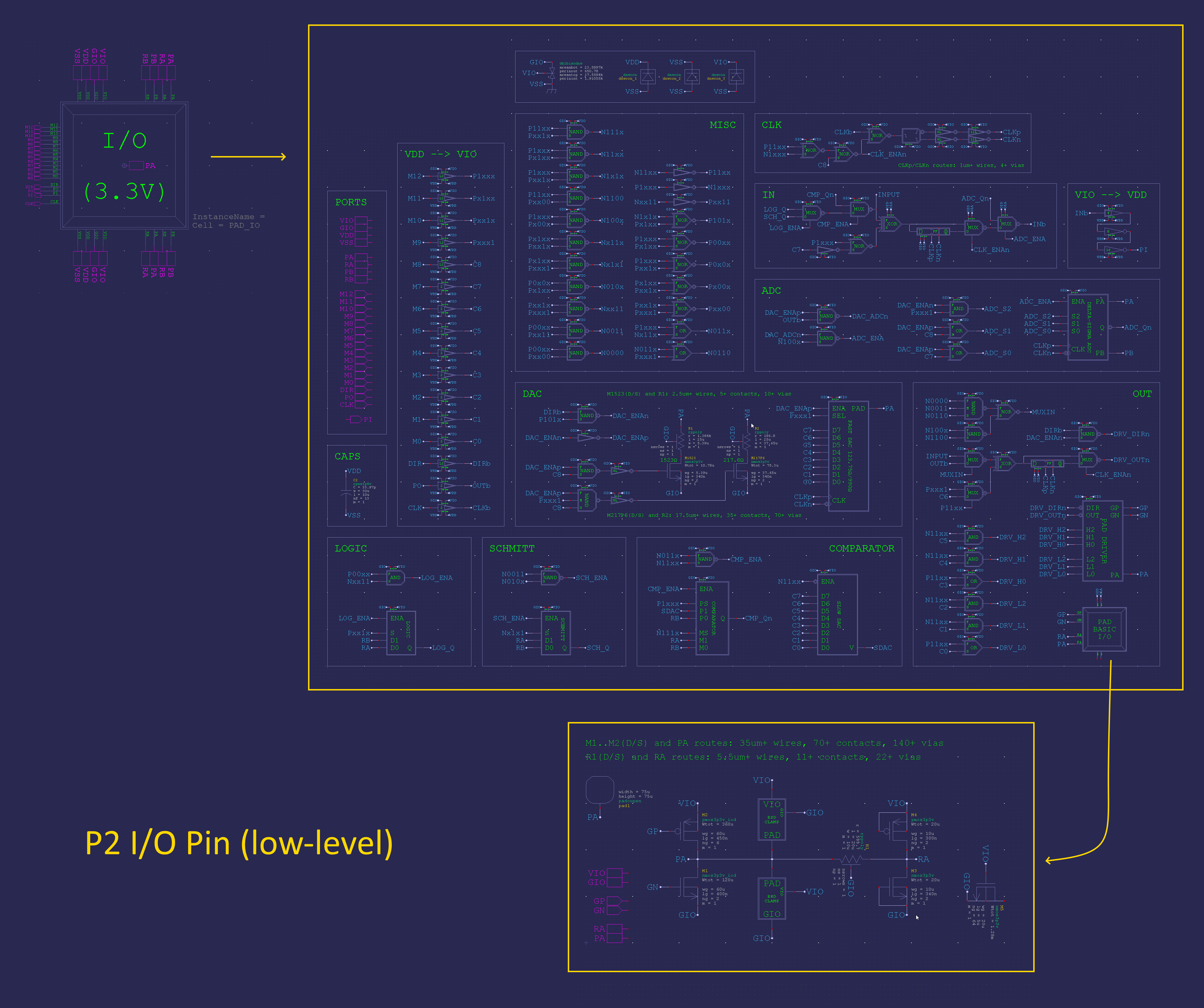
We also have a DAC and ADC for every single pin that can also be used in an analog mode. As I wrote earlier in this series, the documentation is not complete yet, so a few areas for certain I/O configurations are missing, especially when it comes to the low level configurations. For a first hands-on experience with pre-production silicon, this is expected to happen. Figure 7 should give you an overview of the smart pin configuration register. But that’s enough theory for now.

Hands On
For our first real-world test, we use our four input buttons. We can light up an LED with a press of a button. For this we will extend our existing SPIN2 code and use all the nice capabilities we have, as controlling an I/O pin for an LED and our prints() function to write strings to a UART. What we want to achieve should be very basic. We read the pin’s state and replicate it to the LED, just four times, one for each LED and button present. Additionally, if a button is pressed or released, we will output a corresponding string. Lets start with the input configuration. As the hardware buttons don’t have their own pull-up or pull-down resistors, we need to use the chip’s internal ones. From Figure 8 and Figure 7 we need to calculate the value for the config register.
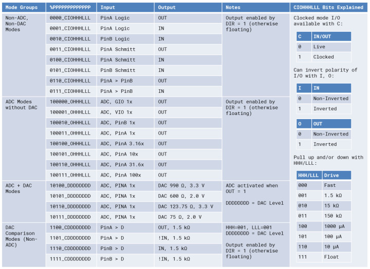
With Figure 5 in mind, we will only have at the end the logic level presented by our pin, so we select input A and B to be the same, non-inverted and to output A without any logic or filtering applied. From the Propeller 2 datasheet, this calculates to 0000 0000 000 000 010 010 00 00000 in binary or 0x900 in hex if we want to use a 15-kΩ pull-up.
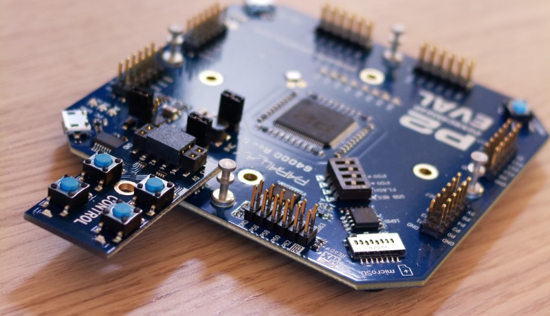
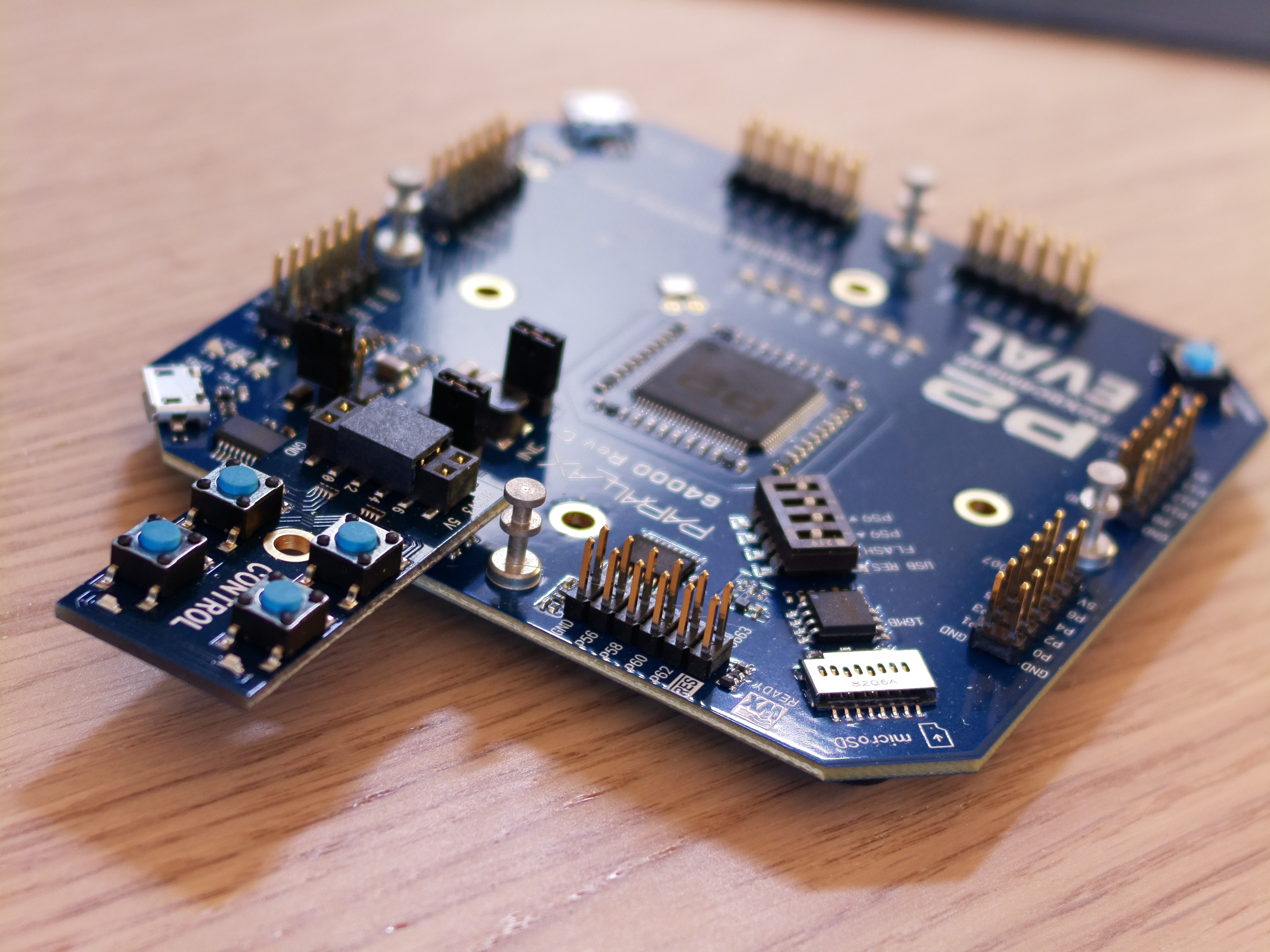
For our code, this means we now add four inputs and use four outputs by attaching out small addon-board (Figure 9) to the Propeller 2 Evaluation board.
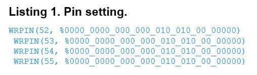
In Listing 1, you can see the modified SPIN2 code to set up our four input pins with pull-ups and the output configuration for our LED output pins.
We use four global variables to store the last read pin level and only send a serial message if a pin has changed. We extend the code we used with two functions, the first to initialize LEDs and the second to initialize our inputs. In Listing 2 you can see four bytes declared to store the state of the four switches connected to the board.

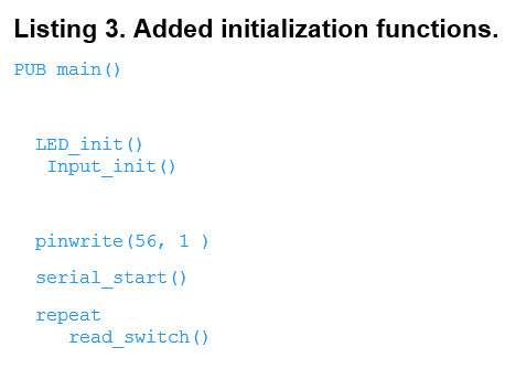
Also, you can see that the code has altered with the two functions for initialization (Listing 3).
The magic to make the inputs work with active pullup capability is hidden inside the bits found in Listing 4.
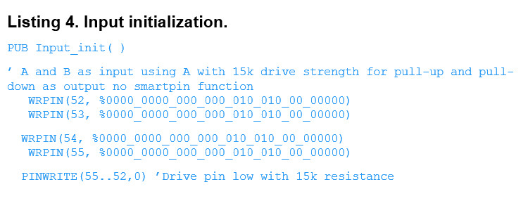
We set the input and output to be driven with 15 kΩ resistance and with the last line set our four input pins to drive low, as we actually use them as output.
After the initialization is done, the function read_switch() is called repeatedly so we have a closer look into the code happening in this function. As seen in Listing 5, the code uses a few IF and IF-ELSE constructs after reading the pin states into the variables a to d.
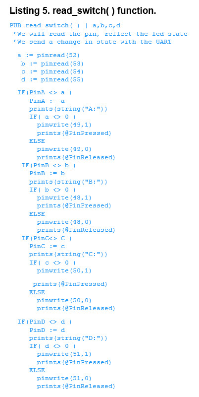
First thing to be done is to detect if a pin has changed by comparing the old stored state with the new one just read. If these values differ, we can assume the state at the pin input has changed and determine if its because the corresponding switch has pressed or released. Depending on the current pin state, we use the prints() function to output “Switch pressed” or “Switch released”. In Listing 5, you can see how our read_switch() looks and works, with simple IF-THEN-ELSE paths for every switch we are using. Also you can read from there that LEDs state is altered according to the new state we have detected.
For now, we’ve done enough with the pins and hope this gives you a little insight into it. This will also be the end of the series for now. As the Propeller 2 is in range of my development bench, it won’t be the last time we write about it or do a short video. As the software and IDE evolve, we will give it some time to grow up. In the meantime, you can access the code developed in this series in our GitHub repository.
Final First Impression
After working with the Propeller 2, I can say it is a powerful MCU that definitly needs more attention to its details than a Raspberry Pi Pico. Using SPIN2 and assembly language is special, and it makes reusing existing C code impossible. Personally, I think it won’t be my MCU of choice for the mainstream projects, but there are defnitly some niches where this chip will be handy.
What about SPI, I²C and HDMI as mentioned in the beginning? As some enhancements in the toolchains take place, it would be interresting to have that finished and move on with improved tools. If you don’t want to wait for the next chapter on the Propeller 2, drop us an e-mail or use one of your favourite social channels to send us a message.
(200479-E-01)
Discussion (0 comments)