
Parking Disk with E-Paper Display: An Innovative Digital Replacement
on
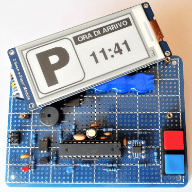
The evolution of the automotive sector, from the point of view of integrating electronic technology into vehicles, has reached extremely high levels. Virtually every functional aspect is optimally managed by sophisticated sensors, digital interfaces, microprocessors and related software. In the cockpit of what can now be considered ‘computers on wheels,’ however, it is still easy to find an indispensable instrument, often made of humble cardboard and operated manually. This is the Time Disk, a device required to indicate the start of parking in regulated areas. Over the decades, this accessory has remained almost unchanged — made of cardboard, plastic or other more noble materials — and only recently have some digital models appeared on the market. The one proposed in the article uses a modern e-Paper display with some special features, such as setting the arrival time with a single button, a message in a choice of four languages, and the on-demand display of the current time and date, the ambient temperature, and the battery level.
The E-Paper Display
A relatively recent invention (1996), e-ink (electrophoretic ink) technology, generally referred to as e-Paper, owes its success mainly to its use in eBook readers, the portable devices that offer an electronic alternative to traditional books, thanks to its paper-like reading experience and perfect visibility even in high light conditions. However, the unique feature that has led to the spread of this technology in other areas is the ability to maintain the display of information for a long time even in the absence of a power supply, allowing the realization of devices that potentially require power only for the duration necessary to update the screen (refresh). Typical applications, increasingly popular in retail outlets, are electronic labels and price tags, often difficult to distinguish from paper ones, which can be updated when necessary, even remotely using wireless technologies. To better understand how electronic ink works, Figure 1 helps us.
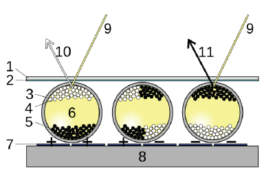
layer, 3 transparent micro-capsules, 4 positively charged white pigments, 5 negatively charged
black pigments, 6 transparent oil, 7 electrode pixel layer, 8 bottom layer, 9 light, 10 white,
11 black). (Source: https://en.wikipedia.org/wiki/E_Ink)
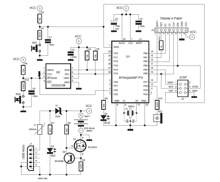
In the simplest, black-and-white display version, positively (white) and negatively (black) charged pigments are suspended in a liquid contained in microspheres representing pixels. Due to the polarization created by an appropriate electric field, the pigments, attracted by the charge of opposite sign (electrophoresis), position themselves to create black or white pixels, composing the desired image. At this point, even if the electric field is removed, the pigments remain in position until a new charge is applied. Visibility, from the particularly wide angle, is achieved by reflection from ambient light, and in the absence of this, a special light source is required. Interestingly, however, under direct sunlight, the screen update does not take place correctly. On the basis of this operating principle, numerous types of displays have been realized, even large and full-color ones, which are, however, still very expensive. At the same time, the affordable offer of smaller, black-and-white, grayscale or limited-color displays by specialist retailers has increased. On the other hand, the interest of DIY enthusiasts in these components has not increased as much, from what I have been able to see on the Internet. In my opinion, the reason for this is to be found in various critical points, which also became apparent during the development of this project, due to factors such as the excessive number of models, versions, sizes, drivers and color combinations on the market, the lack of well-documented and easy-to-implement libraries for the various development platforms, and often fragmentary and insufficient information and support from the manufacturers themselves. Despite this, by choosing among the best supported products and stubbornly applying ourselves as Makers, it was possible to achieve a result that I believe could be interesting. Let us therefore continue with the analysis of the circuit diagram, shown in Figure 2.
Schematic Diagram
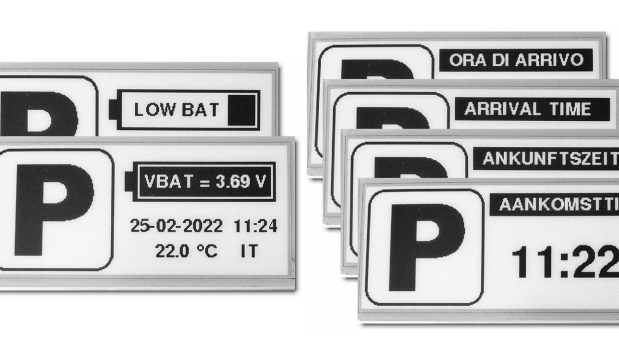
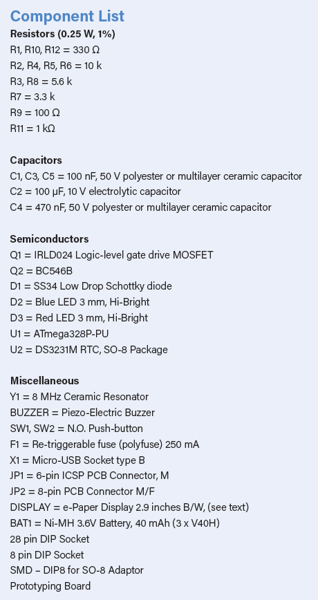
An ATmega328P microcontroller was chosen to manage the display, the same as the one used in the Arduino UNO board, given the availability of a versatile library specific to this platform. The MCU operates at a clock frequency of 8 MHz, thanks to the external ceramic resonator, and is normally in a power-saving state (SLEEP_MODE_PWR_DOWN), to ‘wake up’ only if the display needs to be updated. The DS3231M Real-Time Clock (RTC) integrated circuit, on the other hand, remains active at all times, capable of maintaining, as long as it is powered, the date and time with an accuracy of ±5 ppm (±0.432 seconds/day). Other notable features include a temperature sensor, a dual alarm and extremely low current consumption, in the order of microamps (µA) in the configuration used, Single Supply (VBAT Only). It communicates with the microcontroller via an I2C interface and dedicated library. The SW2 button (blue in the prototype) ‘wakes up’ the MCU, which can thus receive data on the current time and show it on the display, together with the message ‘TIME OF ARRIVAL’ and the ‘P’ logo, before returning to sleep mode. A short beep from the buzzer confirms the operation of the button while the blue LED D2 remains lit for the duration of the event. SW1 (red in the prototype), on the other hand, produces a hardware reset of the ATmega328P, followed immediately by the display of a screen showing the ‘P’ logo, the battery symbol and voltage, the ambient temperature, the current time and date, and the language selected for the message, as per the example in Figure 3.
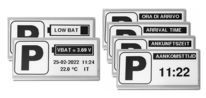
The same screen is automatically displayed every 24 hours (at the desired time, thanks to the RTC alarm function) in order to perform a complete refresh of the display, recommended by the manufacturer, and to check the battery status and the correct operation of the entire system. Therefore, we can define SW2 as “parking button” and SW1 as “info button.” Resistors R1 and R10, with capacitors C1 and C5, help to suppress any noise due to bouncing of the button contacts, whereas R2, R4, R5, R6 are pull-up resistors. C2, C3 and C4 are the usual power supply bypass capacitors of the ICs. R11 limits the current drawn by the reset terminal of the specific display used. JP2 is the connector to the display, while JP1 allows the upload of firmware by connecting a USBasp programmer. Due to the low current consumption, the power supply for the prototype is provided by a small 3.6 V Ni-MH rechargeable battery with 40 mAh capacity. The circuit formed by Q1, Q2, R8, R9 is a constant-current regulator with low voltage drop, which limits the charging current to about 6 mA, a value that this type of battery can withstand without any inconvenience even if the expected 14...16 hours of charging are exceeded. A micro-USB socket allows the connection of a common 5 V charger, via a resettable protection fuse, while D1 diode prevents the ‘backflow’ of current from the battery. LED D3 indicates that the device is charging. However, we will go into the power supply topic in more detail later.
Practical Realization
The prototype of the Parking Disk with e-paper display was made as usual on a prototype board, as can be seen in Figure 4. Of course, this is only one of many possibilities; by using SMD components and a special printed circuit board, one could probably achieve a smaller size, slightly larger than the display. The battery and buzzer are located under the e-Paper module, while the eight-pin connector of the same is obtained from a section of male and female strip contacts. The integrated circuits are socket-mounted, and a readily available adapter was used for the DS3231M, in an SO-8 housing. Maximum freedom for the choice of an enclosure, as long as it is equipped, of course, with a transparent window!
parking disk with e-paper display.
As far as the e-Paper module is concerned, as already mentioned, it is sometimes difficult to find our way around in the very wide range of apparently similar components on offer. The one used in the prototype is visible in Figure 5. It is a Waveshare 2.9-inch diagonal, black and white, 296 x 128 resolution. It has a built-in logic level converter and supports partial refresh, an indispensable feature in this project. Models other than this one may not guarantee the same results I obtained, or may require modifications to the firmware or wiring diagram. Also to be considered is the permitted operating temperature range, which in this case extends from 0 to 50°C.
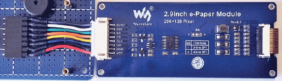
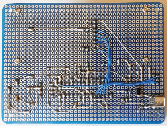
Figure 6 shows the soldering side of the prototype, on which D1 diode (SMD type) and the micro-USB charging connector are also located.
Coming back to the subject of power supply, the choice of a rechargeable Ni-MH battery, not quite a recent technology, is mainly motivated by the search for higher safety and reliability in the not always optimal conditions of use on a vehicle. Compared, for example, with Li-Ion batteries, the albeit remote danger of explosion is null and even the performance at low temperatures is better. Standard charging is certainly slower, but easier to handle. In any case, given the minimal currents involved and the operating voltage of the circuit, which can vary between 3.3 V and 5.0 V without any problems, a solution involving three AAA alkaline batteries in series should also be considered, eliminating the need for the charging circuit and still being able to rely on a duration that is likely to exceed the car’s! Quantifying accurately the ‘consumption’ of increasingly popular battery-powered devices that alternate between periods of activity and pauses in power-saving mode (also referred to as sleep-mode, power-down, hibernation, low-power) is not straightforward; unfortunately, inserting a multimeter in series with the power supply and taking a current reading is not enough. The basic calculation to be performed in order to obtain the average value of the current drawn, and thus an estimate of battery life, can be represented with the following pseudo-formula:
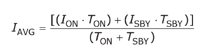
where IAVG represents the average current, ION the activity current, ISBY the stand-by current, TON the activity time and TSBY the stand-by time.
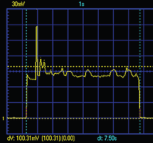
I ‘captured’ the trend of the active current with the oscilloscope (see Figure 7) by detecting the voltage drop at the ends of a low-value precision resistor in series with the power supply, obtaining, with acceptable approximation, the figure of 10 mA for a time of 7.5 seconds, which represents the duration of a display cycle.
The quiescent current, measured with a digital multimeter instead, amounts to as little as 3 µA. Assuming we will be using the parking disk four times a day, plus the refresh cycle, we get a total uptime of 7.5 x 5 = 37.5 seconds and a rest time of (24 x 3600) - 37.5 = 86,362.5 seconds over 24 hours. We therefore obtain:
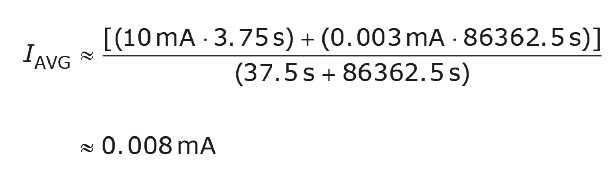
A 40 mAh battery — leaving aside for the sake of simplicity the reduction in capacity due to self-discharge, a drop in nomina voltage, temperature variations and other factors — at an average current of 0.008 mA could ideally power the circuit for approximately 40 /0,008 = 5.000 h (i.e., more than 200 days or at least six months)! Realistically, even a duration reduced to half would be a good result. Convenient online applications are now also available for this type of calculation. I provide a link to one that I have found to be among the most effective and practical.
The Firmware and Its Functionality
In this project, the source code 008000"> is written with the Arduino IDE 1.8.19 and requires, for proper compilation, the installation of the Arduino core MiniCore v2.1.3 and some specific libraries. The core used allows a more efficient and versatile management of the ATmega328P microcontroller and above all optimizes the memory usage of the compiled code, which comes to occupy 31,264 of the 32,768 bytes of program memory (Flash) and 1,501 of the 2,048 bytes of dynamic memory (SRAM), almost at the limit of this MCU’s possibilities.
It should be noted that this project is not feasible, even by trial and error, with an Arduino Uno board, since part of the latter’s memory is used by the bootloader to allow direct programming, while for the ‘barebone’ microcontroller we use an external USBasp programmer. Speaking of memory, the keyword PROGMEM appears several times in the listing, referring to the byte arrays of the bitmap and text character strings, which are read-only data. By declaring these arrays as PROGMEM, functions can access these data by reading them directly from Flash memory, without first copying them into the much smaller SRAM, which then remains available for ‘dynamic’ execution of the program. The DS3231M 1.0.6 library is used for communication with the integrated real-time clock (RTC), while the GxEPD2 1.3.6 library, supported by the GFX_Root 2.0.0 graphics library, has been chosen for the basic management of the e-Paper display.
The latter must be overwritten with the one supplied with the project, which has modified fonts. The GxEPD2 library is a massive piece of work and unfortunately lacks a structured documentation, which is to be found instead in the code of the available examples, which are very numerous, but at first glance daunting due to their apparent complexity, which is then discovered to be due to the attempt to extend compatibility to as many display models as possible. I have therefore attempted to do a summary job, extrapolating only the functions and definitions necessary for the type of display used in the project. These can be found in the file Waveshare_29_BW_avr.h, while the file ParkBitmap128x128.h contains the array of bytes, obtained by means of a special converter, representing the bitmap image of the parking logo (capital P inscribed in a square with rounded corners, size 128 x128 pixels, black/white). These files, available for download, reside in the sketch folder, together with the main source code file Disco_Orario_e-Paper.ino, in which there are also links to the core and library sites, extensive comments on the code, and other indications that I found useful. I advise readers interested in the details of the listing to examine it by opening it with the Arduino IDE (or their favorite editor). Instead, here I would like to illustrate the operation of the program in a more descriptive manner, with the help of the flowchart in Figure 8.
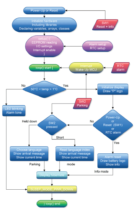
Keeping in mind that the circuit is always connected to the battery, the first time it is switched on (Power-Up), the initialization operations and the setup() function are executed, with the activation of an Interrupt, and then the loop() is executed.
At the start of the loop, the ambient temperature is checked. If it is not within the expected range, an acoustic and luminous alarm signal is emitted, then the microcontroller is placed in maximum energy-saving mode (SLEEP_MODE_PWR_DOWN). Otherwise, the loop() continues by initializing the display, showing the ‘P’ logo, battery status, current date and time, temperature and the language selected for the incoming message, showing what we can call info mode, after which the display is ‘hibernated’ (again for energy saving), the MCU switched off and the loop() aborted. From this state, the microcontroller can be ‘woken up’ (Wake Up) by a hardware reset (with the SW1 button) or by an Interrupt, an event generated in this case by the RTC’s daily alarm function or by the SW2 button. If the resumption is caused by the reset or the alarm, the loop() restarts from the beginning and always ends in info mode. On the other hand, if the microcontroller is reactivated via SW2, the loop() restarts, initializes the display, shows the logo and if the button was pressed and immediately released, shows the arrival message and the current time, in what we will call parking mode. Keeping SW2 pressed, on the other hand, will display the messages in the four languages in succession. Simply release the button when the desired one appears, and the setting will be stored in EEPROM until the next change. The current time will then appear, and the cycle will always end in parking mode. An example of the screenshots can be seen in Figure 3. We have seen how the current date and time are provided and maintained by the RTC DS3231M integrated circuit, which must still be programmed after the first application of the supply voltage and in case the supply voltage fails. In order to simplify the firmware and the circuit, avoiding the addition of further buttons, the programming of the date and time is carried out at the same time as the sketch is loaded, by means of a special line of code inserted in the setup() routine:
DS3231M.adjust(DateTime(2022, 03, 02, 19, 10, 00));
The format to be used is of the type “YYYYY,MM,DD,hh,mm,ss”. Once you have entered the correct data, you can load the sketch, check the date and time, comment out the line (add the double slash at the beginning) and reload the sketch, this is to avoid the clock reverting to its initial settings at every reset. To achieve sufficient accuracy, simply measure the time it takes to upload the code, say 30 seconds, and then start the first upload 30 seconds in advance. With a few tries, a synchronization per second can be achieved at ... no cost! The daily refresh time is also set from code, simply by entering the desired time.
Finally, a note on the method used to measure the battery voltage. It is often found on the Internet, with some variations, and Microchip itself documents it in its own note. The ‘trick’ is to set, via the appropriate registers, the internal reference voltage (1.1 V) as the ADC’s input value and the voltage to be measured (VCC) as the reference. Any change in VCC will change the ADC reading, allowing the voltage value to be calculated with enough accuracy.
Final Considerations: E-Paper Tech
Although offering features of undoubted interest, which make it particularly suitable for the project presented, e-Paper technology also has certain limitations, the most obvious of which is the low refresh rate. The model used here performs the complete refresh cycle in 2 seconds and the partial refresh in 0.3 seconds. These values cannot therefore compete with other display types in the visualization of rapidly changing images, graphics and text. Finally, as I often say, beyond the actual usefulness of the proposed object, I hope that you have found some interesting ideas to elaborate and reuse with the attitude of a Maker, and that this article has triggered your desire and curiosity to experiment with e-Paper displays!
This article appears in Elektor May/June 2023. Do you have technical questions or comments about this e-paper displays or anything else covered in this article? You are welcome to contact the author or the Elektor editorial team.
Discussion (1 comment)