
The PbMonitor Battery-Monitoring System: A Solution for UPS and Energy Storage Applications
on

A Practical Solution
Energy storage systems, particularly those utilized in UPS configurations, frequently employ multiple batteries in series to meet voltage requirements. While this topology simplifies power delivery, it introduces significant challenges related to charge balancing, individual cell health monitoring, and state-of-charge (SoC) disparities. Conventional UPS systems treat the battery bank as a singular entity, lacking the granularity required to detect cell-to-cell imbalances, which can precipitate premature failure and reduced operational efficiency.

The impetus for developing the PbMonitor battery-monitoring system (Figure 1) grew from a practical necessity: my UPS system comprises four 12-V lead-acid batteries connected in series to yield a nominal 48-V supply (Figure 2). However, without a dedicated battery-monitoring system, individual battery voltages remained unknown, introducing risks of overcharging or undercharging specific batteries. With nearly one and a half years of operation, it became imperative to implement a system capable of diagnosing battery health, identifying performance deviations, and facilitating proactive maintenance.

12-V lead-acid batteries in series
The motivation for this battery-monitoring system project stemmed from my own use of lead-acid batteries, which highlighted the need for a dedicated monitoring solution. This inspired the name PbMonitor, with “Pb” representing lead, aligning with the core focus of tracking and optimizing lead-acid battery performance.
Beyond UPS environments, PbMonitor’s application extends to renewable energy systems. By implementing a monitoring framework, battery lifespan can be extended, predictive maintenance strategies can be optimized, and the overall reliability of energy storage solutions can be improved.
Battery-Monitoring System Architecture
The PbMonitor battery-monitoring system is built around the ESP32-C3 microcontroller, which provides reliable Wi-Fi and BLE communication capabilities for real-time monitoring. To ensure high-resolution voltage and current measurements, the MCP3008 external ADC by Microchip is integrated, offering 10-bit precision across eight channels and interfacing with the ESP32-C3 via SPI, as shown in the block diagram (Figure 3).
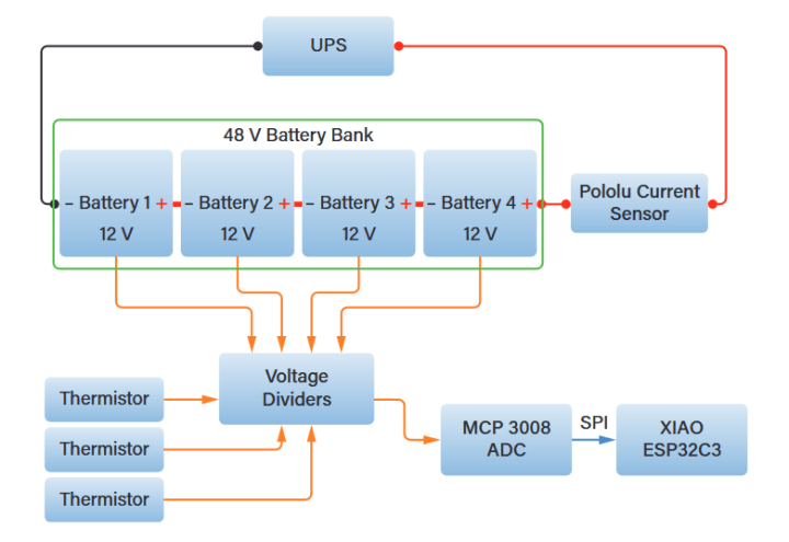
Voltage readings are obtained using a network of precision resistors forming a voltage divider, allowing compatibility with the ADC’s input range. For current measurement, the system employs the Pololu ACS72981 module (chip by Allegro MicroSystems), a high-precision Hall-effect current sensor module that enables bidirectional current tracking, critical for monitoring charge and discharge cycles. This current sensor module was also used in the AmpVolt project series and proven to be a reliable sensor for current measurements.
Additionally, thermistors are integrated to continuously monitor both environmental and battery temperature, providing crucial thermal data for battery longevity and operational safety. The monitored battery bank consists of four 12 V lead-acid batteries arranged in series to create a 48-V system, requiring discrete voltage tracking to prevent imbalance.
Battery-Monitoring System Schematic
The schematic (Figure 4) follows a structured approach to battery parameter acquisition. Each battery node is connected to a voltage divider circuit (R1 to R8) to scale the voltage down to a range suitable for the MCP3008 ADC (IC1), which operates at a 10-bit resolution with an input voltage limit of 0 to 3.3 V. In a series-connected battery system like this, measuring individual battery voltages can be challenging due to the shared connection points. To simplify the measurement process and reduce hardware complexity, voltage is measured at the positive terminal of each battery relative to the system ground. This method provides cumulative voltages (e.g., 12 V, 24 V, 36 V, and 48 V). The MCP3008 ADC (IC1) sequentially samples these voltages, which are then processed in the firmware by subtracting each battery’s voltage from the one before it.
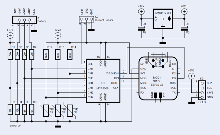
This approach eliminates the need for complex differential voltage sensing circuits, reduces the number of ADC channels required, and avoids floating ground issues that can arise when measuring individual cell voltages directly. Additionally, it ensures accurate readings without introducing isolation challenges that come with direct cell measurement, making it a practical and reliable solution for multi-battery monitoring systems.
The Pololu ACS72981 ±50-A current sensor at K2 is used to measure bidirectional current flow, providing real-time data for both charging and discharging cycles. This Hall-effect sensor outputs an analog voltage that varies with current. At 0 V, the output voltage is 1.67 V, serving as the reference point. When current flows clockwise (discharging), the voltage increases at a rate of 0.0264 V per amp, while a counterclockwise (charging) current results in a proportional decrease in voltage.
The sensor’s output is read by the MCP3008 ADC, which digitizes the voltage for processing. The MCP3008 ADC, operating at 3.3 V, is configured for single-ended mode, using all eight channels for battery voltage, current, and temperature measurements. The ADC has a 10-bit resolution and a maximum sampling rate of 75 kSamples/s at 3.3 V; but, when all eight channels are used, the effective per-channel sample rate is reduced due to sequential sampling. With an SPI clock of 1 MHz, the ADC can achieve a practical sample rate of approximately 9 to 10 kSamples/s per channel, ensuring reliable real-time monitoring.
Temperature monitoring is implemented through thermistors (T1...T3) also connected to the MCP3008, ensuring continuous tracking of both environmental and battery conditions. The thermistor operates as part of a voltage divider, where its resistance changes with temperature, altering the measured voltage. To obtain the thermistor resistance, the voltage across it is measured using a voltage divider circuit. The resistance is calculated using the formula:

where Rfixed is the known series resistor value, Vmeasured is the voltage drop across the thermistor, and Vref is the reference voltage. This voltage is used to calculate resistance, which is then converted to temperature using the Steinhart-Hart equation:

where T is temperature in Kelvin, R is thermistor resistance, and A, B, C (provided in the thermistor’s datasheet) are thermistor-specific coefficients. The temperature is finally converted to Celsius. Using thermistors is more effective than using 1-wire-sensors, as they are fast and accurate.
Moving to the MOD1, the XIAO ESP32-C3 by Seeed Studio was an obvious choice for this project due to its compact size, powerful ESP32-C3 architecture, and well-designed form factor. Seeed Studio has done a quite good job in creating these XIAO series boards that are not only small but also highly versatile, with a good balance of IO options for integration into various applications. Its ability to be directly soldered onto a PCB or plugged in using 2.54 mm headers makes it extremely flexible for both prototyping and final implementations.
The XIAO ESP32-C3 (MOD1) is connected to the ADC via SPI, applies calibration algorithms, and transmits data via MQTT to a Home Assistant server. An OLED screen connection K3 (2.54-mm pitch) is also provided for showing the real-time data on site. Finally, an AMS1117 (T1) LDO by UMW is used to power the entire system.

PCB Layout
The PCB was designed to be compact, measuring 53.5 × 36 mm. The goal was to keep the board as small as possible so that it does not appear overwhelming when connected to the system. As seen in Figure 5, the PCB layout strategically positions the Pololu current sensor module on the right side. To facilitate voltage sampling, 2.54-mm pitch horizontal JST connectors were used, ensuring secure and reliable connections. The same connector type was used for the thermistors. The OLED display connector was placed in the middle of the board for optimal visibility, while the XIAO ESP32-C3 module was positioned on the left side to ensure efficient space utilization and signal integrity. The layout was optimized to minimize noise, ensuring stable ADC readings and reliable operation in demanding environments.

Software Integration and Home Assistant
The firmware for PbMonitor is developed using the Arduino framework and is compatible with the Arduino IDE and PlatformIO, ensuring ease of development and deployment. The sketch, along with the complete hardware files, is available in the project’s GitHub repository. The firmware relies on several essential libraries, including WiFi.h for network communication, SPI.h for interfacing with the MCP3008 ADC, Adafruit_MCP3008.h for ADC handling, MQTTPubSubClient.h for MQTT communication with Home Assistant, as well as Adafruit_GFX.h and Adafruit_SSD1306.h for real-time OLED display updates.
The firmware also calculates a State of Charge (SoC) using the battery voltage thresholds and is designed for future State of Health (SoH) estimation, which will involve tracking charge/discharge cycles and degradation over time. Additional planned features are discussed in the Future Improvements section below.
Various parameters in the software are configurable, including ADC calibration factors, MQTT update intervals, and threshold values for battery alerts. The firmware applies calibration algorithms to convert raw ADC values into real-world voltage and current measurements, using predefined scaling factors based on voltage dividers and sensor characteristics. The precision of voltage measurements is within ±0.05 V, while current measurements, obtained from the ACS72981 sensor, have a resolution of 0.0264 V per A, allowing accurate detection of even small current variations.
The processed data are transmitted to Home Assistant via MQTT, allowing seamless integration into a smart home environment. The MQTT topics are structured for easy integration, allowing real-time monitoring of battery voltages, current, and temperature. Figure 6 shows how the data is displayed on the Home Assistant Dashboard, where users can track battery performance and receive alerts when critical thresholds are met, by creating automations in Home Assistant.

For users looking to set up MQTT integration with Home Assistant, it has been previously documented the step-by-step procedure in another article, where I implemented the same method for an ESP32-based Energy Meter. That guide can be referenced for setting up MQTT configurations, authentication, and data visualization within Home Assistant.
Monitoring Batteries with PbMonitor
UPS systems charge lead-acid batteries using a multi-stage charging process to maintain battery longevity and efficiency. The charging process typically consists of three stages: bulk charge, absorption charge, and float charge. During the bulk charge phase, the UPS supplies a high current to rapidly charge the batteries until they reach approximately 80% of their full capacity. In the absorption phase, the voltage is held at a constant level while the current gradually decreases, allowing the batteries to reach full charge without overheating. Finally, in the float charge stage, the UPS maintains a trickle charge to compensate for self-discharge, ensuring the batteries remain fully charged without overcharging.
Despite the batteries being fully charged, the UPS continuously supplies a 1 A trickle current. This small current prevents sulfation, a common issue in lead-acid batteries where lead sulfate crystals form on the battery plates, reducing capacity and efficiency. By maintaining this low-level charge, the UPS ensures that the batteries remain in optimal condition for standby use.
To test the charging and discharging cycle, I fully charged the battery setup and ran it on backup mode. The UPS provided a backup duration of 4 hours and 40 minutes before depletion. The collected data during this full charge cycle (Figure 7) showed that Battery 1 and Battery 4 reached a charge voltage of 13.5 V, while Battery 2 and Battery 3 charged up to 14.23 V and 13.9 V, respectively. This discrepancy indicates an imbalance in charging, which could be due to variations in internal resistance or differences in aging between the batteries.

During discharge, notable voltage differences were observed. Battery 1 dropped to 8 V approximately 40 minutes before the end of the discharge cycle, while battery 4 dropped to 8 V just 10 minutes before full discharge. In contrast, battery 2 and battery 3 maintained higher voltages, each stabilizing at 11.5 V by the end of the discharge cycle. These differences suggest that battery 1 and battery 4 may have reduced capacity or higher internal resistance, leading to earlier voltage drops compared to the other two batteries. This imbalance emphasizes the importance of real-time monitoring to detect weak batteries and take corrective action before the system performance is compromised.
Future Improvements
Several enhancements can be made to PbMonitor to improve accuracy, reliability, and usability. On the software side, as seen in Figure 7, the current readings fluctuate significantly, bouncing between zero and the actual value. Since clamp meter measurements remain stable, this issue needs further investigation. Implementing filtering techniques such as moving averages or adjusting the ADC sampling rate could stabilize the readings. Additional software refinements include integrating a button to toggle between different display views, refining the SoC (State of Charge) and SoH (State of Health) algorithms for better accuracy, and implementing internal logging to track historical data. Adding predictive analytics to estimate battery backup time and performance degradation trends would also enhance the system.
For hardware, the current PCB layout is compact but has only three mounting holes, which may not provide sufficient structural stability. Increasing the board size slightly and incorporating four mounting holes would improve enclosure mounting. Additionally, adding two more thermistors would allow monitoring of all four batteries instead of just the middle two, providing a more complete thermal profile. Future iterations could also include a real-time clock (RTC) for precise logging of charge and discharge cycles, along with EEPROM or SD card storage for long-term data retention. Expanding connectivity options, such as Bluetooth or LoRaWAN, could enable remote monitoring, while integrating a buzzer or LED indicators could provide real-time alerts for voltage anomalies. Furthermore, while keeping the Home Assistant MQTT feature, a web server feature should be added for locations where Wi-Fi or Home Assistant is inaccessible, providing a small dashboard on the ESP32 web server to keep track of system status.
Editor's Note: This article (240704-01) appears in Elektor May/June 2025.


Discussion (2 comments)