
Pico Power: Get to Know the Raspberry Pi Pico Board and RP2040
on
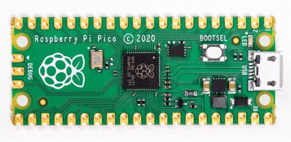
The Raspberry Pi is well known as a single-board computer (SBC) running Linux on it, but the new Raspberry Pi Pico (see Figure 1) is different. While still a Raspberry Pi, Pico is entering a world where the Arduino, the STM32 BluePill board and ESP32 set the standards in terms of price, the software ecosystem, or connectivity. The Raspberry Pi Pico is a bridge from your high-power Linux-based SBCs to the world of embedded microcontrollers.
Another Raspberry Pi?
We will say in advance: the Raspberry Pi Pico is not meant to replace any existing Raspberry Pi; it is meant to be an extension and a companion for the existing Raspberry Pi family. Although it is a Raspberry Pi, this one is completely different from what we have seen until now. The Raspberry Pi Pico is a dual-core ARM powered board that offers just the bare circuitry to make it work. Even if it sounds like a modified Pi Zero, it is not. The Raspberry Pi Pico is not using a Broadcom CPU like the other Raspberry Pi boards we have seen. This one uses a chip, the RP2040, that was designed in-house by the Raspberry Pi Foundation itself.
The RP2040 is a dual-core ARM Cortex-M0+ microcontroller. This core is not a Linux-capable SoC like we have seen before. The Raspberry Pi Pico is entering the field of microcontrollers, where Arduinos, STM32 BluePill boards, and ESP32-based boards are most used nowadays, while RISC-V-based SBCs (like the GD32VF103) are getting increasingly popular. This one is affordable, with a pricetag of around €5, which puts in it in the range of a cloned Arduino Nano and the STM32 BluePill. And it is less expensive than an ESP32 Pico Kit.
In this article, we’ll have a look at the specifications and features of the Raspberry Pi Pico and its RP2040. Be sure to check out the unboxing video from Clemens Valens on Elektor’s YouTube channel [1] and a helpful overivew [2].
A first look at the Raspberry Pi Pico
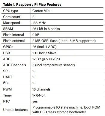
As we already mentioned, the Raspberry Pi Pico features a dual-core Cortex-M0+ microcontroller able to run up to 133 MHz. While dual-core Cortex-M MCUs are not uncommon these days, they usually don’t have two Cortex-M0+ inside but rather use the more powerful Cortex-M4, Cortex-M7, or the newer Cortex-M33 cores.
The RP2040 MCU used on the Raspberry Pi Pico follows the naming scheme shown in Figure 2.
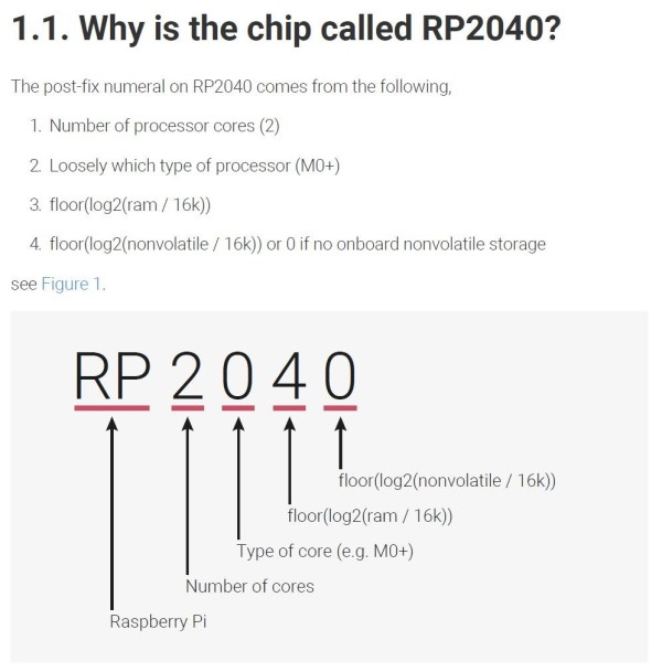
We can only speculate what other parts may follow, as this suggests that there may be more variants to come. We asked the Raspberry Pi Foundation if more variants will follow, but we haven’t received an answer yet. The technical specifications for this MCU are shown in Table 1.
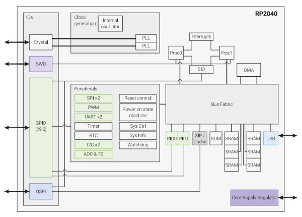
An overview of the peripherals and function blocks inside the RP2040 is shown in Figure 3.
One of the unique things that may be overlooked at first is the absence of flash memory inside the MCU. On the Raspberry Pi Pico, there is a small IC next to the MCU — a W25Q16JUXIQ NOR-Flash with 2 MB storage. The RP2040 supports up to 16 MB for external storage, so increasing storage is a matter of replacing the flash chip. The Raspberry Pi Pico features a USB Port that can be configured as Host or Slave in USB 1.1 mode (12 Mbit/s), allowing to attach USB peripherals or to act as USB device.
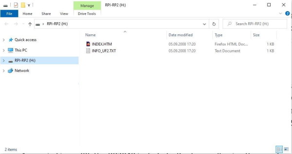
The RP2040 contains a boot ROM, allowing the user to upload new code from a computer. To avoid any kind of special programming tool, the integrated bootloader will show up as mass storage device and the RP2040 can be programmed by simply copying new firmware files into the device (Figure 4), a simple and convenient way to program devices.
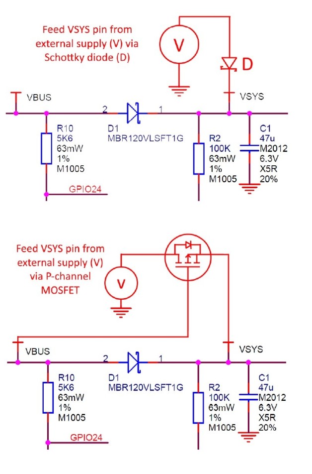
The power supply is also user-friendly. You can power the device from 5 V through micro-USB. It also accepts voltages from 1.8 V up to 5.5 V using an DC/DC Buck-Boost converter on its VSYS pin. This also allows the use of a rechargeable lithium battery or just a set of two or three NiMH batteries. From the datasheet [3], Figure 5 shows the options to connect various power sources.
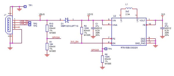
The DC/DC Buck-Boost IC used is an RT6150, whose datasheet can be found at [4] and makes it possible to operate with only a few components, as seen in the schematic shown in Figure 6.
The 40 pins of the Rasberry Pi Pico are on the sides of the board, making 26 GPIOs, including three ADC inputs of the RP2040’s IOs accessible. The other pins are for power and ground. The maximum IO voltage for the Raspberry Pi Pico is 3.3 V on all GPIO pins. On the bottom side of the PCB (Figure 7), every pin is labeled.
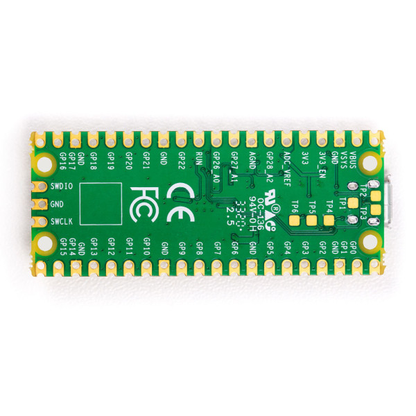
There are three additional pins on the Pico board (SWCLK, SWIO and GND) for the Serial Wire Debug port, which allows for programming the RP2040 and also for debugging.
Peripherals and the Programmable Input/Output block
The Raspberry Pi Pico with its RP2040 includes a set of the most common peripherals you would expect to find: two UARTs, two I²C-Controllers, two SPI controllers, 16 PWM channels, a 12-bit ADC with 500 ksps, an integrated temperature sensor, a real-time clock, timer and the basic GPIO functions. Also included and less common is the USB interface, working as host and slave, and eight Programmable IO (PIO) state machines.
The state machines can be used to implement various interfaces like (additional) UART, I²C, I²S, and SPI, but also SD-Card, VGA, DPI and many more. The RP2040’s datasheet includes a dedicated section explaining their usage and example programs. Figure 8 shows one block containing four state machines.
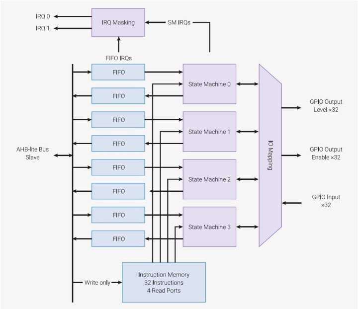
These state machines can execute a set of nine commands: JMP, WAIT, IN, OUT, PUSH, PULL, MOV, IRQ, and SET. As these state machines can run independent from both CPU cores, it allows to form interfaces not supported by the build-in hardware, while offloading work from the CPU cores.
The native UARTs in the RP2040 are based on the ARM Primecell UART (PL011), which is also used on other Raspberry Pi boards, allowing a maximum speed up to 961.6 kBaud. For the two SPI interfaces an ARM Primecell SPI (PL022) is used that is also integrated in other Raspberry Pis. This interface can transfer data up to F_CPU/2 SPI clock in Master mode. The I²C controller included supports Standard mode (100 kHz), Fast mode (400 kHz), and Fast mode plus (1 MHz) clock speeds with 7-bit and 10-bit addressing as master or slave. These three interfaces provide connectivity to most external hardware used and provide a good balance between functions and devices complexity.
The ADC in the RP2040 is a basic SAR with 500 ksps at 12-bit resolution. It has four inputs and a temperature sensor. If you are used to the ADCs of an AVR (for example), you normally find a bandgap reference, providing 2.56 V or 1.1 V to your ADC as reference voltage; here the ADC_AVDD pin on the RP2040 is used. On the Raspberry Pi Pico board, this means an external voltage must be supplied as a reference. The implementation on the Raspberry Pi Pico is shown in Figure 9, as this pin is connected with a resistor to 3.3 V and some filtering.
Another interesting feature is the USB interface provided on the RP2040 and therefore on the Raspberry Pi Pico. The Pico can be configured to be either host or slave it offers up to 12 Mbit/s transfer speed in USB1.1 mode. This enables usage of USB devices like mice and keyboard and USB connectivity to a PC or Raspberry Pi. For the USB Host mode, the controller supports the use of USB Hubs, so you are not limited to connect just one device to it.
The RP2040 has one dedicated 64-bit timer, that runs on a 1 µs time base. This allows to setup to four alarm timers or can be used to generate delays in µs range. For repeating timed events or interrupts you can use one of the eight 16-bit PWM units, each with two channels. Figure 10 shows the block included in one PWM unit.

The GPIO pins for PWM, can also be used for frequency and duty cycle measurement, to generate interrupts, DMA requests and feature a fractional clock divider for more accurate frequency adjustment.
For more advanced programming the RP2040 includes a DMA unit that allows data transfer in the system without the intervention of the CPU cores. For example, AD-conversions and moving results to a pre-defined buffer in memory is possible without the CPU, or sending data from memory to a UART. Also copying larger number of buffers inside the RP2040 from one place to another can be done without the CPUs involved and are even faster than the CPUs could do. This also comes in handy if you need to shift data to an externally connected display. As the DMA unit can also be chained with the Programmable IO (PIO) state machines this forms a mighty setup for high-performance data exchange with external devices.
Schematics, manuals and design files
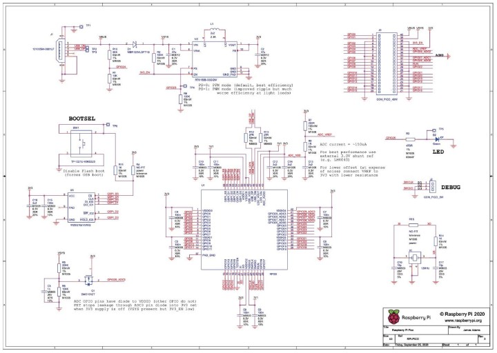
The Raspberry Pi Pico board is the first RP2040 board. Figure 9 shows its schematic diagram. The MCU is surrounded with the DC/DC converter, external QSPI NOR-Flash memory, and some circuitry to measure supply voltage and to set the power converter into low power mode and an USB interface.
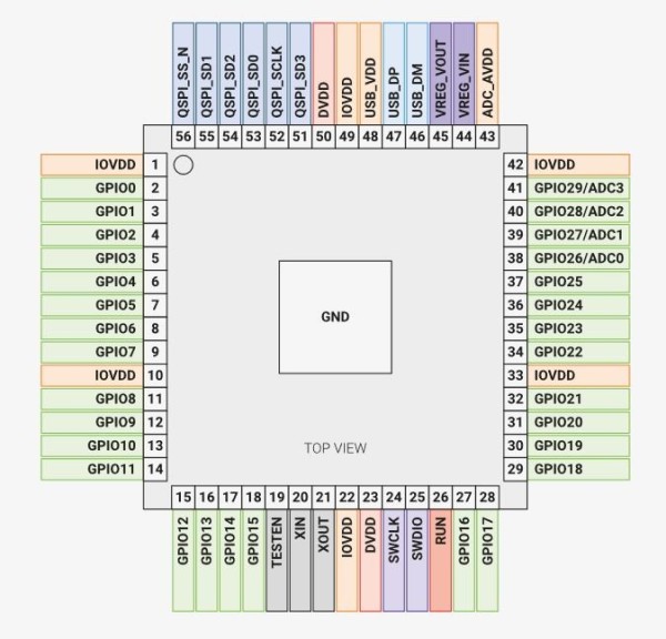
The Raspberry Pi Foundation also supplies KiCad and Fritzing files to get started with your own designs. Interesting to see that you get a reference design that is not the Raspberry Pi Pico but a demonstration on how to make your own board with the RP2040. If you are designing hardware you know that for most other microcontrollers, no special attention was paid to the pin arrangement. However, with the RP2040, PCB designers will thank the Raspberry Pi Foundation for combining associated pins into groups that can easily be routed to external hardware. Figure 11 shows the pin arrangement, and you can clearly see that hardware design was also kept in mind.
At the time we are writing this article, both manuals and software are not in final versions, so minor changes or additions might occur in the meantime. Nevertheless, you can clearly see that this is a Raspberry Pi product with documentation that is ready and complete from the beginning and the hardware is open. Besides this, it also means that from the beginning an open SDK is provided that allows development on your Raspberry Pi, your Linux- or Windows-powered PC, and an Intel-based Mac. Currently, to develop your own applications, you have the choice between MicroPython and C/C++.
Developing with MicroPython
Many RP2040 programmers will prefer C/C++ (or in the near future, the Arduino IDE, because support has already been announced). However, MicroPython is also an option if you want to program this microcontroller. First of all, you’ll need a Raspberry Pi 4 running Raspberry Pi OS or — according to the manual — an equivalent Debian-based Linux distribution running on another platform. You can either build your own Raspberry Pi Pico MicroPython port following the instructions in the manual [5] or download a pre-built binary from the Pico getting started pages [6].
Connecting the board to the Raspberry Pi 4 using a micro-USB cable with the BOOTSEL button pressed presents the Pico board as USB mass storage device. The binary file can then be dragged onto the board to program the flash. After this installation, you can connect to the Raspberry Pi Pico in the MicroPython Interactive Interpreter Mode (also called REPL) via USB or the Pico’s UART.
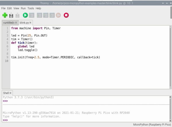
Alternatively, the MicroPython port to Raspberry Pi Pico and other RP2040-based boards works with commonly used Integrated Development Environments (IDEs) like Thonny (Figure 12). The manual contains instructions on how to install and configure this IDE for MicroPython programming with the RPi Pico.
Are you interested in MicroPython? In the book Get Started with MicroPython on Raspberry Pi Pico (G. Halfacree and B. Everard, Raspberry Pi Foundation 2021), you will learn how to use MicroPython to write programs and connect hardware to make your Raspberry Pi Pico interact with the world around it. (Refer to the related products listed at the end of this article.)
Using C/C++ development on a Pi with a Pi
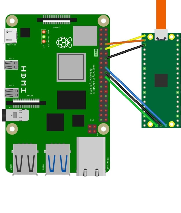
Developing with C/C++ is intended to be done on a Raspberry Pi 4 by the description and tools provided. Setting up a development environment on other systems is described in the manual [7], but for the Raspberry Pi a handy script can be downloaded [8] that will deal with all the steps required for installation. The connection between the Raspberry Pi 4 and Raspberry Pi Pico is done according to Figure 13. In this setup the Raspberry Pi 4 will act also as debug interface using a patched version of OpenOCD. If you like to use a PC or Mac, a debug probe can be built using a second Raspberry Pi Pico as described in the manual.
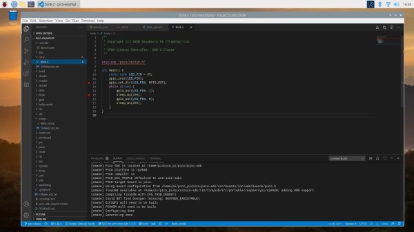
Those that like an IDE more than just developing in a shell, Visual Studio Code (Figure 14) will be installed by the provided script, offering an IDE to get started. At the time we are writing this article, following the examples has worked quite well, but the project generator to start new ones without having to do all kinds of stuff manually on a command line is not completely ready for prime time. Even if you may experience some small hick-ups at launch, like we have seen with the Raspberry Pi 4, there will surely be improvements over time as more users will use the provided software and report bugs.
For the RP2040 a rich set of libraries and examples is provided to get you started with the chip, so you do not have to write drivers for every part of the chip yourself. Also, for the USB the TinyUSB library is included and extended to support the RP2040, allowing a fast entry. The good thing is, as all the code is open, you can dig around the files and study how things have been done. If you are more used to an Arduino Wiring compatible framework, this has currently, at the time of writing, not arrived, but as for other non-Arduino platforms of interest, it will be a matter of time until this will show up.
If you are running on a PC or Mac and want to start developing, the experience gained is to use a virtual machine to set up the develop environment. If you struggle at some points, you can switch back to a snapshot taken to have a known good system within a short time.
Final thoughts on the Raspberry Pi Pico
Have you been staying away from microcontrollers because they seem to be expensive or less well documented? You do not have an excuse any longer. Grab some Raspberry Pi Picos while they are available and start coding. At a price of €5 per unit and with all the support and documentation provided by the Raspberry Pi Foundation, it is not a question of whether you should buy it, but rather how many Pico boards you should buy. Due to the accessibility of datasheets, development tools, examples, and beginner-friendly manuals, working with a Pico is quite enjoyable. It is not restricted to experienced developers; it can be used to teach kids and students. If you start new projects with the board, let us know and share your experience. We are curious to see what you can come up with.
Web Links
[1] C. Valens, “Raspberry Pi Pico Review,” Elektor.TV, 1/21/2021.
[2] C. Valens, “Now Playing at a Theatre Near You: RP2040 in Raspberry Pi Pico,” ElektorMagazine.com, 1/22/2021.
[3] The Raspberry Pi Pico datasheet
[4] RT6150 datasheet
[5] Pico MicroPython manual
[6] Pico Getting Started
[7] C/C++ setup
[8] IDE setup script
[9] RP2040 datasheet
[10] Pico Getting Started datasheet


Discussion (7 comments)