
Presence Detection Simplified: A DIY Radar-Controlled Lighting Project
on

The HLK-LD2410 Radar Module
You surely know those automatic lights controlled by PIR sensors. They switch on when you pass in front of them and switch off automatically when movement is no longer detected. Practical as they may be, they do have a mind of their own, making them behave a bit quirkily sometimes. With the introduction of low-cost radar-based human-presence detectors, it has become possible to solve some of the issues that a PIR sensor has. Radar detectors provide real presence detection even when you’re not moving, keeping the light on when you’re reading on the toilet. It’s radar, so it’s immune to false positive detections due to changing light conditions, a bee, moving hot air, etc.The HLK-LD2410 sensor is such a high-sensitivity human-presence sensing module. It works in the 1.2-cm wavelength a.k.a. 24 GHz amateur, amateur satellite, radio location, and Earth-exploration satellite service band far from the busy 2.4-GHz Wi-Fi band. Developed by Hi-Link Electronics, the module provides human body detection for home automation systems. Its working principle is based on frequency-modulated continuous wave (FMCW) radar to detect both moving and stationary human bodies.
FMCW Radar Theory in a Nutshell
The radar is based on two working principles. First, it uses the Doppler effect to detect objects. A continuous wave (CW) signal is transmitted, then reflected by conducting materials such as metal or water, and thus also by human bodies. When the reflecting object (the target) is moving, the wavelength of the reflected signal (and therefore its frequency) changes proportionally to the speed of the target. This is known as the Doppler effect. We all know it from the sound of cars and trains passing by. The pitch of the sound is higher when the vehicle comes towards you and lower when it moves away.
Measuring the distance of a target with a CW radar can be done by adding frequency modulation (FM). When the signal frequency is swept up (or down) linearly, the received reflected signal will not have the same instantaneous frequency as the transmitted signal because it is delayed. The two frequencies are slightly different, and this difference is proportional to the distance between the transmitter and the target. However, since there is also the Doppler effect, this method only works accurately for static or slow-moving objects.
All the complexity from the above explanation is reduced inside the HLK-LD2410 module to a single digital output indicating the detected target state. The output is high when a person is detected, moving or not. The application using the radar module can therefore remain simple, as it only has to react to a binary state.
Presence Detection Circuit
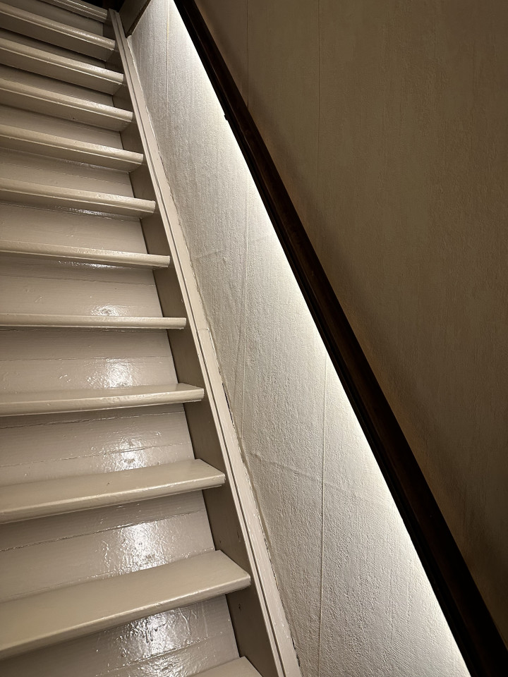
The presence detection application described in this article is an automatic light for a staircase (Figure 1). A radar-based human-presence detector switches the light on when a person is detected, and off otherwise. Furthermore, the system must only work when the ambient light intensity is low (i.e., darkness detection). The schematic of the circuit is shown in Figure 2.
A light-dependent resistor (LDR, R2) is used to detect darkness. When it is dark, the resistance of R2 is high, much higher than the value of R1 + P1, so the voltage on IC1’s gate is high. This turns on IC1, resulting in P-channel MOSFET T1’s gate being pulled low. T1 starts to conduct and switches on MOD1, a low-cost DC-DC converter module. Now, MOD2, the radar module, switches on too, and the detection of human presence is activated. The circuit is thus armed. This situation is indicated by LED1.
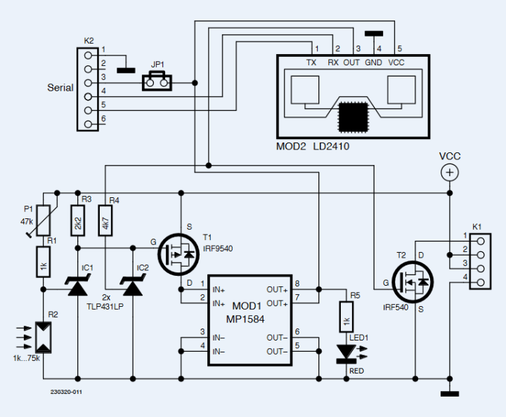
In the absence of humans, the output of MOD2 is low, N-channel MOSFET T2 blocks, and the load (an LED string) is not powered. When a human body is detected, the output of MOD2 goes high and switches on T2, which, in turn switches on the load. Pretty straightforward, isn’t it?
Disco Lights
There is one thing, though, which is that when the light is switched on, the LDR no longer sees darkness. The voltage on the gate of IC1 drops and IC1 switches off. This powers down the rest of the circuit and the light switches off. Now the LDR sees darkness and it switches on IC1, etc. The system starts to oscillate. To avoid this disco lighting effect, R4 and IC2 have been added. IC2 has the same function as IC1, except that it is controlled by the output of the radar module instead of by the LDR. IC1 and IC2 have open-collector outputs and can therefore be connected in parallel to drive T1 in a wired-OR configuration.
As soon as a person is detected, IC2 is switched on. This will keep the circuit powered in the same way as IC1 did, even when IC1 switches off. The light will switch off only when the human presence has disappeared. This assures that the circuit has two stable states.
Power Supply
The circuit is intended to drive a basic LED string with a DC voltage up to 24 V. The supply voltage is to be connected to pins 3 (+) and 4 (−) of connector K1. The load connects to pins 2 (+) and 1 (−).
The radar module requires 5 VDC. Therefore, MOD1, a cheap MP1584 DC-DC converter module, is used to lower the LED string supply to a suitable value for the radar module. MP1584-based DC-DC converter modules can be found online in many variations, adjustable or with a fixed output voltage. Either can be used, even when the output voltage is not 5 V, as it is enough to change a resistor value to obtain a 5 V output. Use the following equation to calculate the resistor value:

Here, RA is the resistor between pin 4 of the MP1584 IC and Vout; RB is the resistor between pin 4 and GND. On the module used for our prototype, RB had a value of 8.2 kΩ. Since the module was configured for a 12 V output, RA had a value of 115 kΩ. To lower the output to 5 V, RA must have a value of 43 kΩ. On our prototype, this could be arranged for by soldering a 68 kΩ resistor in parallel to RA. Another way is to replace RA with a 39 kΩ resistor in series with a 3.9 kΩ resistor (when RB = 8.2 kΩ).
PCB
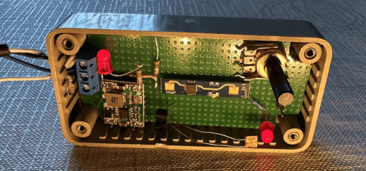
At the Elektor lab, we designed a small printed circuit board (PCB) for the project with test points for checking some vital signals. The board fits in a cheap, plastic (ABS) 1591XXA enclosure from Hammond (Figure 3). The radar features good shell penetration and does not require holes in front of it. This allows for a more aesthetic enclosure. Although the sensitivity is focused in front of the antenna, if you want to avoid detection from the back, shield the rear with a piece of metal (film).
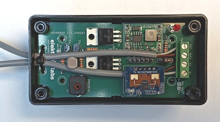
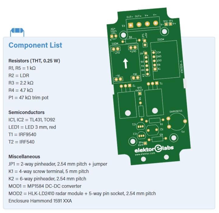
The HLK-LD2410 radar module comes in at least two different shapes (Figure 4): a 16×22 mm board with a large 5-way 0.1″-pitch pin header and as a 7×39 mm long and narrow board with a small, 0.05″-pitch connector. Even though either type can be used, their connectors are not wired the same way. The first type’s signals are ordered TX, RX, OUT, GND, and VCC, while the second has OUT, TX, RX, GND, and VCC. The PCB is wired for the first type, but has room for the second type. The long and narrow module we ordered came with an adapter cable that can easily be connected to the PCB. Therefore, both types can be used without too much fiddling.

Power connector K1 is intended to be mounted “looking down,” meaning that the power supply and light wires run down over the PCB to the opposite, short side. The two holes on that side can be used for strain relief with e.g. a cable tie or so (see Figure 3), but if you want to do things another way, feel free to.
Configuring the Radar
The HLK-LD2410 module works out of the box, but it can be configured over a serial port with a Windows program named LD2410 Tool [2]. This explains the presence of connector K2, a serial port wired up for a 3.3 V FTDI-compatible USB-to-serial cable.
The radar module must, of course, be powered before you can configure it, and there are two ways to do this: from the USB-to-serial cable (JP1 closed) or from the circuit’s power supply (JP1 open). In the second case, ensure that the LDR sees darkness; otherwise the circuit will not turn on. Use P1 to adjust the light intensity (the level of darkness) that turns on the circuit.
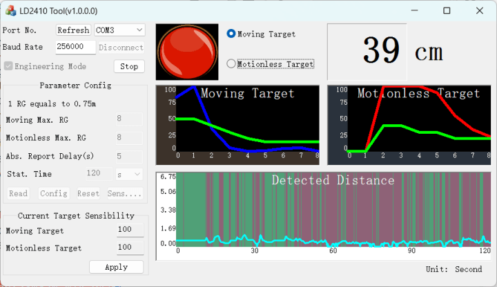
With the radar module powered, you can configure it. First, connect to the module. The tool has two main modes. To align the radar, it’s best to enable Engineering Mode and click Start (Figure 5). This then shows live sensing in two graphs. On the left, the moving target and on the right, the motionless target. The detection aperture is divided into eight gates of 75 cm each. The sensitivity of each gate can be set from 0 to 100, where 100 is the least sensitive (meaning “disable this gate for detection”). If the blue or red line reaches or crosses the green line, the output pin switches to a high level. When you’re satisfied with the chosen sensitivity levels, click Config to save the settings to the sensor persistently.
That’s it, your human presence detector is ready for use (Figure 6). Another idea for an application would be a red light / green light motion detector (just like in the popular TV series Squid Game), where a person must be in a certain location but is not allowed to move. Enjoy!
Questions About Presence Detection?
Do you have technical questions or comments about his article? Email the author at ginodelek@gmail.com or contact Elektor at editor@elektor.com.
Editor's Note: This article (230320-01) appears in Elektor May & June 2024.


Discussion (0 comments)