
DIY Programmable Video DAC: Handle Any Format Up to RGB888
on
When you experiment with microcontrollers and VGA-quality video for retro gaming or some other application, you will need a digital-to-analog converter (DAC). This flexible design lets you try out all sorts of video formats before fixing the final resolution.
A Simple DAC
In the not-so-distant past, if you wanted to add a video output to your computer system, you needed special video ICs. But today, almost any microcontroller can produce a VGA video signal on the fly. The resolution and color depth depend on the amount of available RAM and the speed of the MCU. A simple digital-to-analog converter (DAC) is all that is needed to turn the digital bit streams into analog voltages for the red, green, and blue channels of the VGA monitor.
The DAC’s required word width will be determined by the target video signal’s resolution and color depth. These two parameters, in turn, depend on the computing resources available in the MCU generating the video signal. What your system is capable of may not be clear at the start of the project, and so you might prefer to start with a narrow-word DAC. On the other hand, when a project is almost done, you may find that there is room left to improve the quality of the video signal. In that case, you would want a DAC with a greater word width.
The circuit presented here can be used in both situations, and everything in between. It’s a 3-channel video DAC with programmable word width, where each channel can be set up independently of the others. Therefore, it can be used for anything from RGB111 up to RGB888 (8-bit resolution for all colors). Each digit can take on any of the values in the range 1 to 8, e.g. RGB535 and RGB221 are possible video color formats. Web Update: Please note that the value of R66 is incorrectly reported on the schematic drawing. R66 = 536 Ω as indicated on the Component List.
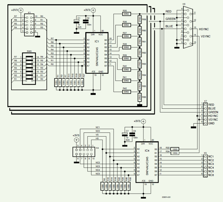
The Circuit
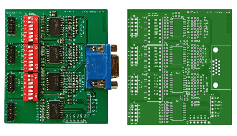
The circuit is shown in Figure 1. It shows only one color channel (red), as it is the same for each color. The digital video enters at K1 with up to eight bits per channel. The bits are buffered by IC1, which drives an R2R resistor ladder DAC. The DAC output is a video signal in the range from 0 V to 0.7 V. Pull-down resistors at the inputs ensure that unconnected bits are seen as zeroes.
The number of bits per color is set with the SW3 dip switches. For an 8-bit signal, all the switches should be off. To reduce the word width, close the switches starting at the bottom with the one that is labeled R1 and R0. As an example, for a 4-bit word width, close the four lower switches. Connect the bits top-down, i.e., connect the most-significant bit to R7, G7, or B7, respectively, and then work your way down. Doing things this way ensures that the video output can always reach its maximum value (0.7 V) instead of getting weaker.
IC4 buffers the horizontal and vertical synchronization signals. The remaining six buffers can be used for something else. They are exposed on K5.
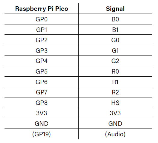
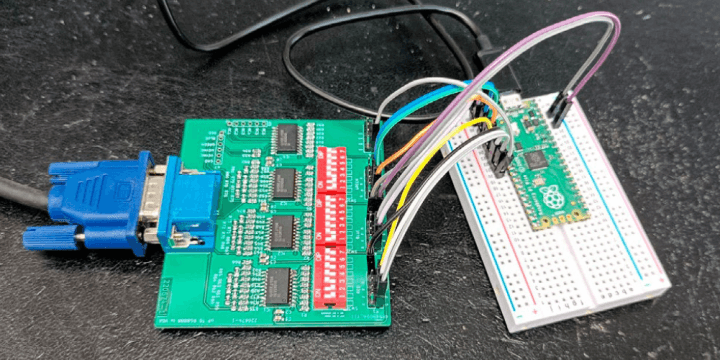
To try out the video DAC quickly without spending hours on programming, connect it to a Raspberry Pi Pico board and a VGA monitor (see Figure 2 and Table 1). Use HSYNC as a synchronization signal. Download a demo from here, program it into the Pico and enjoy the graphics (Figure 3).
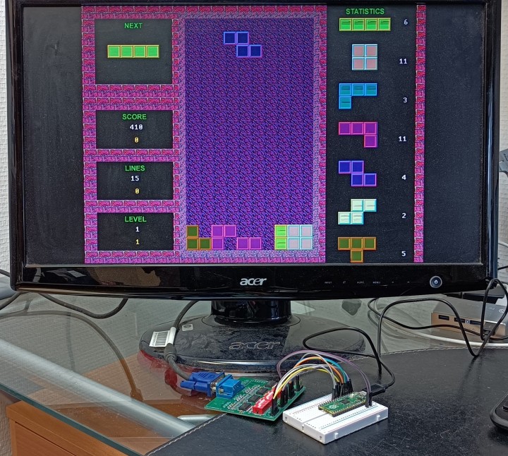
The demos on are in RGB332 format. Therefore, you must close the lower five switches for red and green and the lower six switches for blue:
number of switches to close = 8 – word width for color
Some of the demos have sound output on the Pico’s GPIO19. Put a 1.5 kΩ resistor in series with the output and add a 10 nF capacitor to ground to create a simple low-pass filter for the audio signal.
The project design files are available here.
Questions or comments?
Do you have questions or comments about this article? Please contact Elektor at editor@elektor.com.
Editor's note: Mathias Claussen worked on this design, and Clemens Valens handled the text for this article (220674-01). The complete article appears in the Elektor Circuit Special 2023.
Discussion (0 comments)