
Post Project 55: Simple Wind Speed Meter
April 3, 2015
on
on

Wind meters are usually mechanical constructions which usually measure wind direction (with a vane) and wind speed (with a paddle wheel). As an electronics enthusiast you would prefer to solve this without any mechanical components. Here we describe a small circuit which measures wind speed electronically. This uses the fact that moving air (in this case the wind) has a cooling effect on an object that is warmer than its surroundings. Circuit
The sensor in this case is a transistor (T2 in Figure 1), which is connected as a diode by joining the collector and base together. The forward voltage drop of the diode thus created increases by about 2 mV for every degree centigrade of reduction in temperature. When the transistor is now heated somewhat, so that its temperature is a little higher than its surroundings, then the amount of cooling will be determined by the strength of the wind that blows over it.
The heating of T2 is taken care of by transistor T1, through which flows a continuous DC current. The two transistors are thermally coupled to each other. The voltage across T2 — and with that the wind speed — is measured by comparing the voltage across this transistor with the voltage across a reference transistor T3, which is also connected as a diode. The voltages across T3 and T2 are routed to the inverting and non-inverting inputs of opamp IC1. This CA3130 is set to a gain of 1000 through R6 and R5. The output of IC1 drives, via resistor R1, the heater transistor T1. When the wind cools ‘diode’ T2 down, this then increases the voltage drop across this diode. As a result the output voltage of the opamp increases with the consequence that the base current of T1 increases and the amount of heat generated in this transistor goes up. The opamp therefore attempts to compensate the temperature drop by increasing the collector current of T1. By including an ammeter in the collector circuit of T1 we can measure how much T2 is being cooled (or perhaps better: how much additional heat T2 needs from T1). This ammeter can be an ‘old-fashioned’ moving coil meter rated 50 mA or a digital voltmeter module with a suitable current shunt for 50 mA.
In Figure 2 you can see the small circuit board that was designed for the wind speed meter. The layout for the circuit board is a free download, available from [1]. The few components are quickly fitted. T1 and T2 are placed against each other with a lit- tle heatsink paste between them and then clamped together by wrapping a piece of wire around them (refer to the photo of the built-up prototype).
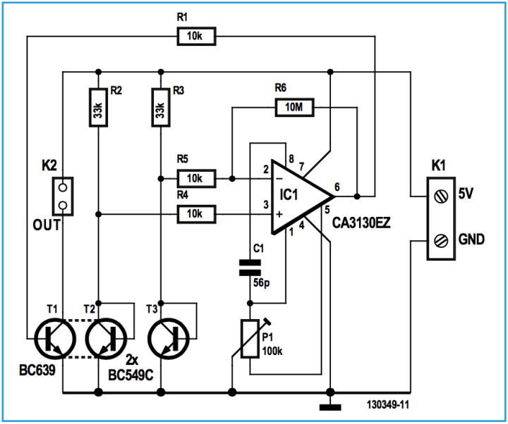
Figure 1: The amount of cooling of a transistor (T2) is determined by the wind speed.
The sensor in this case is a transistor (T2 in Figure 1), which is connected as a diode by joining the collector and base together. The forward voltage drop of the diode thus created increases by about 2 mV for every degree centigrade of reduction in temperature. When the transistor is now heated somewhat, so that its temperature is a little higher than its surroundings, then the amount of cooling will be determined by the strength of the wind that blows over it.
The heating of T2 is taken care of by transistor T1, through which flows a continuous DC current. The two transistors are thermally coupled to each other. The voltage across T2 — and with that the wind speed — is measured by comparing the voltage across this transistor with the voltage across a reference transistor T3, which is also connected as a diode. The voltages across T3 and T2 are routed to the inverting and non-inverting inputs of opamp IC1. This CA3130 is set to a gain of 1000 through R6 and R5. The output of IC1 drives, via resistor R1, the heater transistor T1. When the wind cools ‘diode’ T2 down, this then increases the voltage drop across this diode. As a result the output voltage of the opamp increases with the consequence that the base current of T1 increases and the amount of heat generated in this transistor goes up. The opamp therefore attempts to compensate the temperature drop by increasing the collector current of T1. By including an ammeter in the collector circuit of T1 we can measure how much T2 is being cooled (or perhaps better: how much additional heat T2 needs from T1). This ammeter can be an ‘old-fashioned’ moving coil meter rated 50 mA or a digital voltmeter module with a suitable current shunt for 50 mA.
In Figure 2 you can see the small circuit board that was designed for the wind speed meter. The layout for the circuit board is a free download, available from [1]. The few components are quickly fitted. T1 and T2 are placed against each other with a lit- tle heatsink paste between them and then clamped together by wrapping a piece of wire around them (refer to the photo of the built-up prototype).
Figure 1: The amount of cooling of a transistor (T2) is determined by the wind speed.
Read full article
Hide full article
Discussion (0 comments)