
Start Playfully with RISC-V: How to Run Quake 1 on a Microcontroller
on
What Are We Creating?
The Canaan Kendryte K210 is an inexpensive microcontroller with a RISC-V core. It can be found on the Sipeed Maixduino board or the Sipeed Maix Bit (both available in the Elektor shop), as well as on other boards and can be purchased as a kit with camera and LCD for about €30. We will show on this microcontroller how a toolchain and the SDK can be installed for the board under Linux. In addition to the classic “hello world,” we will use Quake 1, a 3D shooter game from the mid-1990s, and show how this can be translated for the K210. If you just want to try out Quake 1 and don’t want to compile the source code yourself, you can download a ready-made binary from the GitHub repository of elect-gombe [1] and flash it directly.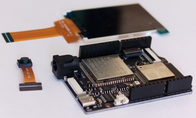
Hardware
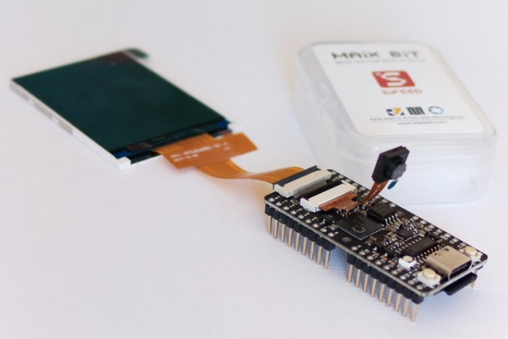
This article uses the Sipeed Maixduino (Figure 1) and the Sipeed Maix Bit (Figure 2), which feature a Canaan Kendryte K210 as the microcontroller. This is a RISC-V-based microcontroller which, according to RISC-V terminology, is equipped with two hearts (processor cores).
The exact technical details can be found in Table 1. In the table, the designation RV64IMAFDC can be found for the processor core. Something that stands out is the designation RV64 at the beginning — and, yes, this is a 64-bit microcontroller.
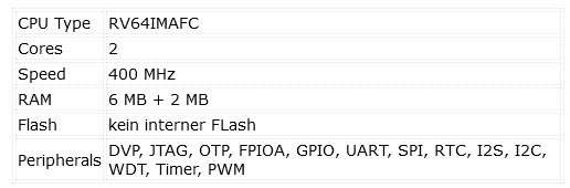
There’s also the internal SRAM, which at 8 MB (6 MB of user RAM + 2 MB of AI RAM) is larger than the internal flash of many other MCUs. As with the Maxim MAX78000, the K210 also has a neural network accelerator. Its use has also already been presented in Elektor [2].
The boards did not skimp on the other equipment either. A camera and an LCD with 320 × 240 pixels are included with both boards. Those who use the Maixduino should note that the WiFi module is connected via the same interface as the SD card. During the tests, at least two SD cards went into an undefined functional state. There are no findings for the Maix Bit yet. Also, not every SD card is suitable here, and it requires a bit of trial and error which card ends up running with the K210.
Toolchain
For the development for a Kendryte K210, we use Linux (Ubuntu 20.04). As a recommendation, the installation in a virtual machine has proven itself here as well. Snapshots made it possible to restore the operating system to a defined state without losing much time. The use of Windows is possible, but not covered in this article.
A compiler and an SDK are required once for the Kendyte K210. Since the K210 is an RV64, a 64-bit RISC-V, it would make sense to use the current GCC for the architecture. Unfortunately, for the K210, the RISC-V GCC compiler and C libraries were modified by Kendryte a few years ago and maintained in a separate GitHub repository. This modified combination of compiler and C library has a few minor customizations that have not been fed back into the main RISC-V GCC and C library branch. Making these adjustments to the current GCC is not impossible, but it is not be part of this article at the moment. We are focused on starting with the K210.
Compile a Compiler
The following commands are entered in a terminal or terminal window. We can clone the appropriate compiler [3] with git clone --recursive https://github.com/kendryte/kendryte-gnu-toolchain on our own computer. The toolchain does not come ready-made, but as source code, which we now have to translate so that it generates code for an RV64 processor.
For this, we need a few packages under Linux. These can be installed with sudo apt-get install autoconf automake autotools-dev curl libmpc-dev libmpfr-dev libgmp-dev gawk build-essential bison flex texinfo gperf libtool patchutils bc zlib1g-dev libexpat-dev.
Now that everything is ready, we change with cd kendryte-gnu-toolchain to the folder that was created by the git clone. Here we configure the compiler with ./configure --prefix=/opt/kendryte-toolchain --with-cmodel=medany --with-arch=rv64imafc --with-abi=lp64f so that it can generate code suitable for the K210. If the command runs successfully, we can compile the compiler with sudo make -j8 where the 8 stands for the number of processor cores of the own computer. The compiler is now compiled and installed in /opt/kendryte-toolchain. The compiler is now finished and ready to use. The terminal can now be closed.
SDK Installation
Once the compiler is installed, now comes the SDK for the Kendryte K210. This again requires a terminal or terminal window. For the SDK there are two choices, one with a FreeRTOS, which is no longer maintained, and a variant without FreeRTOS. For the first steps we need a SDK without FreeRTOS. This is cloned with git clone https://github.com/kendryte/kendryte-standalone-sdk.git. With cd kendryte-standalone-sdk we can now switch to that folder.
The SDK is based on CMake and is operated here with the help of the command lines. As a first test we try to compile the hello world project. With mkdir build && cd build the directory build is created and navigated into. The hello_world provided with the SDK can now be compiled with cmake ... -DPROJ=hello_world -DTOOLCHAIN=/opt/kendryte-toolchain/bin. Afterwards the project can be compiled for the K210 with make.
In the build folder, you will then see two files — once a hello_world.bin and once a hello_world file. The hello_world.bin is meant to be uploaded to the K210; the hello_world files can be used for debugging. Debugging the K210 is a topic for a more in-depth article.
Flash Tools and Serial Terminal
Now that the first source code for the K210 has been successfully translated, it is time to get it onto the board. For this kflash and the kflash_gui (Figure 3) are needed. As in the previous steps, a terminal or terminal window is used to install the necessary software. First, Python3 is needed, and can be installed with sudo apt install python3-pip.
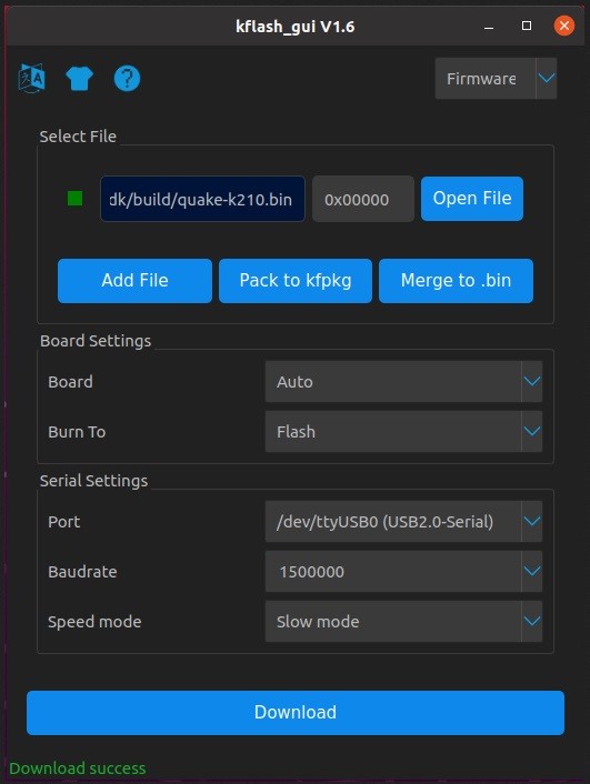
First, kflash is now installed with sudo pip3 install kflash. For kflash_gui, a compiled version can be downloaded from [4]. After unpacking, a terminal can be used to change to the kflash_gui folder and ./kflash_gui to start the program.
To compile the kflash_gui from the current source code the current version of the source code is fetched with git clone --recursive https://github.com/sipeed/kflash_gui.git. With sudo apt install python3 python3-pip the necessary environment for compilation is set up. Since the kflash_gui has additional dependencies, these are downloaded with cd kflash_gui && sudo pip3 install -r requirements.txt. The kflash_gui can now be started with python3 kflash_gui.p
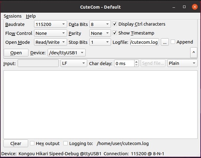
Besides the flash tool, it is very handy to have a serial terminal at hand. CuteCom (Figure 4) from the Ubuntu package sources offers an easy-to-use graphical serial terminal. For installation, sudo apt install cutecom can be entered in a terminal or a terminal window. After successful installation CuteCom is available as an application.
An important step now concerns the serial interfaces under Linux. Normal users do not have the right to use serial ports. To obtain this right, one must become a member of the user group by entering sudo adduser $(whoami) dialout in a terminal or terminal window. This change will only take effect after a reboot.
The First Hello World
After the preparations are done, it’s time to test the hello_world.bin. First, the kflash_gui must be started. Then the board must be connected to the computer with the K210. Depending on the board, one or two serial ports should appear (under Linux /dev/ttyUSBx or /dev/ttyACMx). In the kflash_gui, the corresponding serial port is selected for flashing and then the hello_world.bin. All other settings do not need to be changed. With download the hello_world.bin should now be written to the board. If the process is successfully completed, the CuteCom can be started.
In the CuteCom, the suitable serial interface (/dev/ttyUSBx or /dev/ttyACMx) is opened (115200 Baud, 8N1). After a reset of the K210 now appears Core 0 Hello world and Core 1 Hello world. With this the first Hello world demo is finished — we now know that both processor cores can execute code and we can successfully load code on the K210.
Compile Quake 1 for the K210
Quake 1 [5] is a 3D shooter game from the mid-90s and has shaped the genre with its graphics and game design. The source code for Quake 1 was released under the GPL2 license in late 1999 and has since served as the source of various ports.
The source code contains only the engine itself, but no other files such as graphics or levels. This data can be taken from the Quake 1 shareware version [6], or from an installed full version. Quake 1 can still be purchased DRM free legally at GOG.com [7].
For the K210, elect_gombe (Twitter @elect_gombe) did a port two years ago now. During this time, adjustments and bugfixes were made to the SDK for the K210 which unfortunately lead to the source code no longer running directly in this way. Therefore, here follows an introduction and the necessary adjustments. Before these, a backup should be made of the kendryte-sdk-standalone folder (since the modifications that follow now allow Quake 1 to be compiled, but are not necessarily suitable for other source code).
To translate Quake 1 we have to clone the source code from the Git repository [8] of elect_gombe. For this we open a terminal or terminal window and navigate with cd ~/kendryte-standalone-sdk/src/ into the project folder of the K210 SDK. Here we now clone the source code with git clone https://github.com/elect-gombe/quake-k210.git, so that a quake-k210 folder is created.
Now we have to overwrite some files of the SDK with those from the quake-k210 folder. In the still open terminal we copy a modified linker file into the SDK with cp quake-k210/additionalparts/kendryte.ld ../lds/kendryte.ld. With cp quake-k210/additionalparts/compile-flags.cmake ../cmake/compile-flags.cmake modified compiler flags (i.e., parameters for compiling the source code) are copied into the SDK. This is necessary because the source code of Quake 1 still contains code parts that cannot be compiled with the modern settings of today’s compilers. In the folder ./quake-k210/additionalparts/ there is a crt.S-replace file. This needs a few modifications so that we can use it with the current SDK. With nano ~/kendryte-standalone-sdk/src/quake-k210/additionalparts/crt.S-replace the crt.S-replace is opened. In this file are the first few lines of source code, here assembler, which the K210 executes. Additionally, some interrupts are handled here. Since this file was modified at a time when Standalone SDK and FreeRTOS SDK were still intertwined, there are a few entries here that cause errors when compiling and linking. It is necessary to delete the assembler instructions in the trap_entry section from line 166 to line 160. Between line 133 and line 140 there should be only the following:
133 trap_entry:
134 addi sp, sp, -REGBYTES
135 sd t0, 0x0(sp)
136
137 .handle_other:
138 ld t0, 0x0(sp)
139 addi sp, sp, REGBYTES
140 addi sp, sp, -64*REGBYTES
When the file has been adjusted accordingly, this must be saved with CTRL+O. The editor is then closed with CTRL+X. Now the file is copied to the appropriate place in the SDK. To do this, enter cp ~/kendryte-standalone-sdk/src/quake-k210/additionalparts/crt.S-replace ~/kendryte-standalone-sdk/lib/bsp/crt.S in the terminal.
In the still open terminal, we now change to the build directory of the SDK with cd ~/kendryte-standalone-sdk/build/. In order to have no remainders of earlier projects in the build directory, we empty it with rm * -r. With cmake ... -DPROJ=quake-k210 -DTOOLCHAIN=/opt/kendryte-toolchain/bin the project is now prepared. If we would type make now, the compilation aborts with an error. This is generated by the new compiler flags, and the most obvious thing to do would be to adjust the flags so that the compilation goes through successfully.
The current error comes from the NNCASE library, which is used for neural networks, i.e. AI. Since Quake 1 does not use this library and we need the AI RAM for Quake we can exclude this library from the compilation. For this we change with cd ~/kendryte-standalone-sdk/lib/. With nano CMakeLists.txt now adjustments must be made to the file. The CMakeLists.txt contains in line 5 ADD_SUBDIRECTORY(nncase) this is commented out by a # and results in #ADD_SUBDIRECTORY(nncase). In line 45, TARGET_LINK_LIBRARIES(kendryte PUBLIC nncase) also must be commented out, so that #TARGET_LINK_LIBRARIES(kendryte PUBLIC nncase) is in line 45. CTRL+O saves the adjustments and then CTRL+X exits the editor.
This would now compile the source code and save some memory. Unfortunately, this is not sufficient. If we now would compile the source code, Quake 1 would now try to start and after a short time would give an “Error: OUT of MEMORY!” on the serial interface. Although 8 MB of SRAM are available, this is very scarce for Quake 1. Therefore, the memory distribution must be adapted.
For the adjustment, we open a terminal or terminal window if one is not already open. With nano ~/kendryte-standalone-sdk/src/quake-k210/source/sys_ctr.c the file with the quake_main is opened. In line 378 and line 379, 5.5 MB of RAM are allocated. Here we have to reduce the value. As minimum value we can use MINIMUM_MEMORY here. This value is defined in the Quake source code and determines the smallest amount of memory Quake starts with. For Quake 1 and the shareware version this is sufficient. Line 378 is then parms.memsize = MINIMUM_MEMORY;. With CTRL+O the file can be saved and with CTRL+X the editor is closed.
Now Quake can be compiled. To do this, we change to the build directory in the still open terminal with cd ~/kendryte-standalone-sdk/build/. With make clean the remains of the failed compilation are cleaned up once and a subsequent make will start a new compilation. The result is a quake-k210.bin in the build directory which can now be written to the K210. The klash_gui is used for this purpose. But the game will not start like this. You still have to prepare an SD card by copying the id1 folder from Quake 1. Insert the SD card into the K210 in a de-energized state; the SD card slot is not hot-pluggable. If everything is successfully copied, flashed and assembled, Quake 1 should start after insertion and the demos should run.
Connecting a Modern Gamepad to a Microcontroller
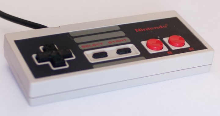
For many applications or games on the microcontroller, it is useful to connect an input device. A mouse and keyboard via the PS/2 interface are one variant. Another one, just as suitable for games and experiments, is a gamepad. If you’re thinking of something simple like the Nintendo Entertainment System (NES) gamepad (Figure 5), a few more buttons never hurt.
And the NES gamepad is truly no standout in terms of ergonomics. One option would be a Nintendo WII Classic Gamepad (Figure 6), which can be controlled via I²C. This would still require a suitable adapter board.

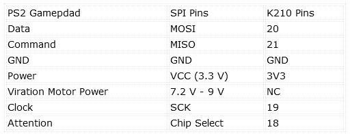
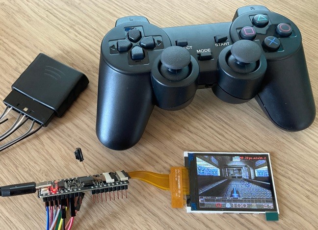
Another option, which is specifically designed for use with the evaluation board, uses a Playstation 2-compatible gamepad (Figure 7). This is manufactured by the Joy-IT company and comes immediately with the appropriate connection cables to connect it to a microcontroller.
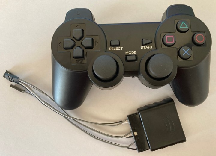
The gamepad, although somewhat hidden to read, uses an SPI interface. The designation from the datasheet can be translated with Table 2 into the corresponding pins of an SPI interface. If you are using an Arduino-compatible controller, you can use the Arduino-PS2X library [9]. This should allow anyone to connect a gamepad for their own projects as well. So a robot arm, a car or a GUI can be controlled with a gamepad.
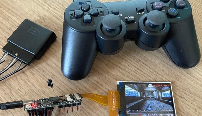
Wiring and Test Run with Quake 1 with Gamepad
The Gamepad is connected to the K210 board (i.e., the Sipeed Maixduino or MAix Bit). Once everything is ready and the SD card is inserted, there is not much standing in the way of a round of Quake 1. If a Maixduino is used, it has so far put a few SD cards into an undefined state between functional and defective during the tests. Since the ESP32, which can act as a Wi-Fi interface on this board, is on the same SPI bus as the SD card, it can be assumed that this unintentionally interferes with the communication. The result can be seen in Figure 8.
Quake 1 on a Microcontroller
While Quake 1 is not to everyone’s taste as far as games go, this game demonstrates the power of the microcontroller. With the SDK and compiler set up, Quake 1 and the first Hello World can now be compiled. This provides a development environment for further experiments with the K210 and source code from which you can see how the periphery of the K210 is controlled.
After the first contact with a RISC-V-based microcontroller, there was still little mentioned about RISC-V, the architecture and the designations. A RV64IMAFC (designation of the processor cores in the K210) sounds in the first moment like something that brings many points in Scrabble, or one would not have thought of anything better to win the game. To decode those designations — and learn more about the advantages of RISC-V — you can have a look at the Elektor article [10] from Stuart Cording. In addition, the article “Embedded System Development with RISC-V Processors” from Allan He (published in Elektor Industry 01/2021) will give you a good overview about the RISC-V ecosystem.
Questions or Comments?
Do you have any technical questions or comments about this article? Email the author at mathias.claussen@elektor.com or contact Elektor at editor@elektor.com.
Discussion (0 comments)