
Tethered Remote Control for a Hoist: Sometimes It’s Not So Simple
on
Need a remote control for a project? Sure, you can score a cheap one on the Internet and have it delivered to your door in a day. But why buy when you can DIY?
My friend Radi knows a thing or two about electricity, but when it gets difficult he calls on me. For his garage, where he works on cars as a hobby, he had bought a used chain hoist at a bargain price. Unfortunately, the remote control was missing, but new ones are available from China at low cost. What he bought was not a perfect match, but in the spirit of ‘if it doesn’t fit, make it fit’ he tried to figure out how to connect everything. He also drew a diagram — and then he phoned me.
His request: “Could you have a quick look the diagram I just sent you by email and see whether it will work?” Initially, I wanted more pictures so that I could get an idea of what the problem actually looked like. And they arrived a short while later, also by email. First let’s look at Radi’s diagram in Figure 1, which is fairly neat for his standards.
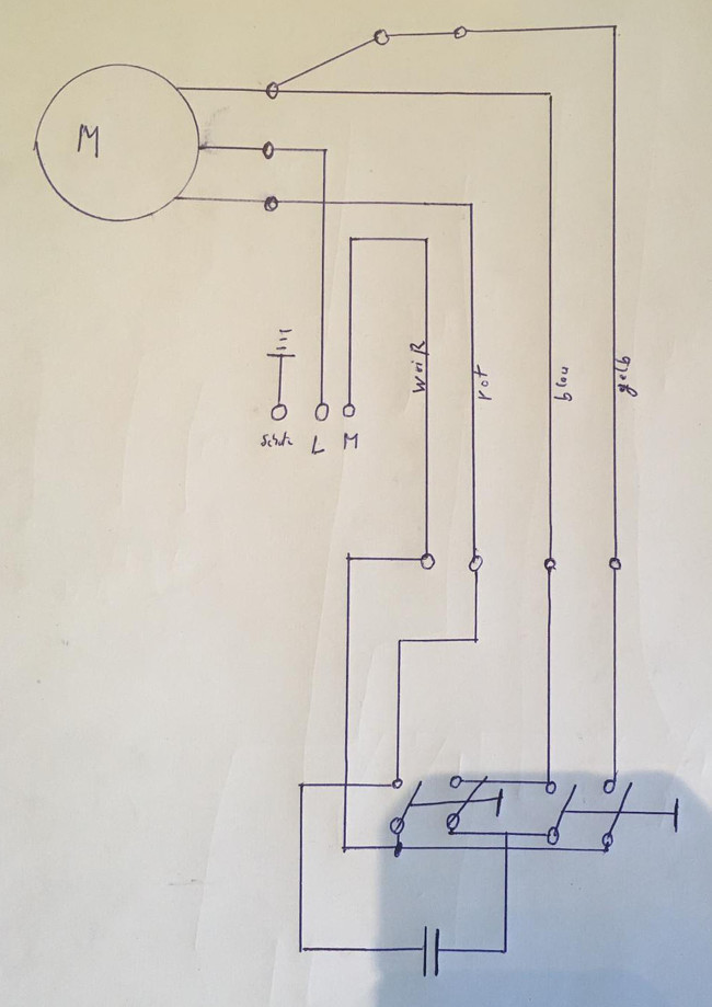
shadow of the iPhone used to take the picture, just to make it more ordinary.
The crux of the problem was that the motor already had a sufficiently long, flexible and sturdy cable and Radi didn’t want to get rid of it, even though it had only four wires — unlike the stiff, low-cost cable attached to the remote control unit. He wanted to be able to control the motor to raise and lower the chain, and he wanted to be able to power the circuitry of the remote control through the four wires. Actually, not so easy as it looks. As a true dyed-in-the-wool electronics enthusiast, I usually turn up my nose at such simple electrical devices, and at first glance I felt totally underwhelmed. But then I thought, let’s first look at the pictures.
Remote Control
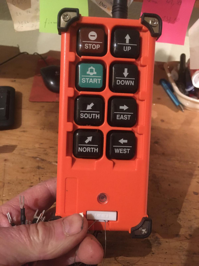
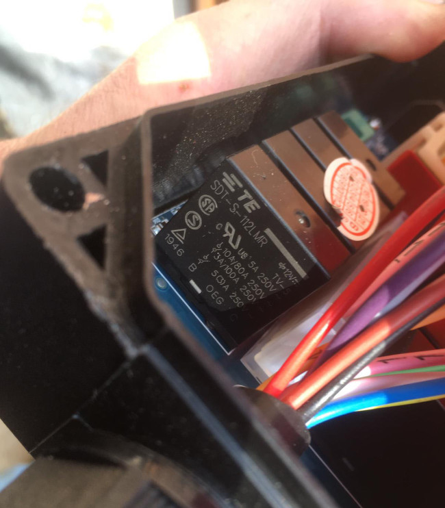
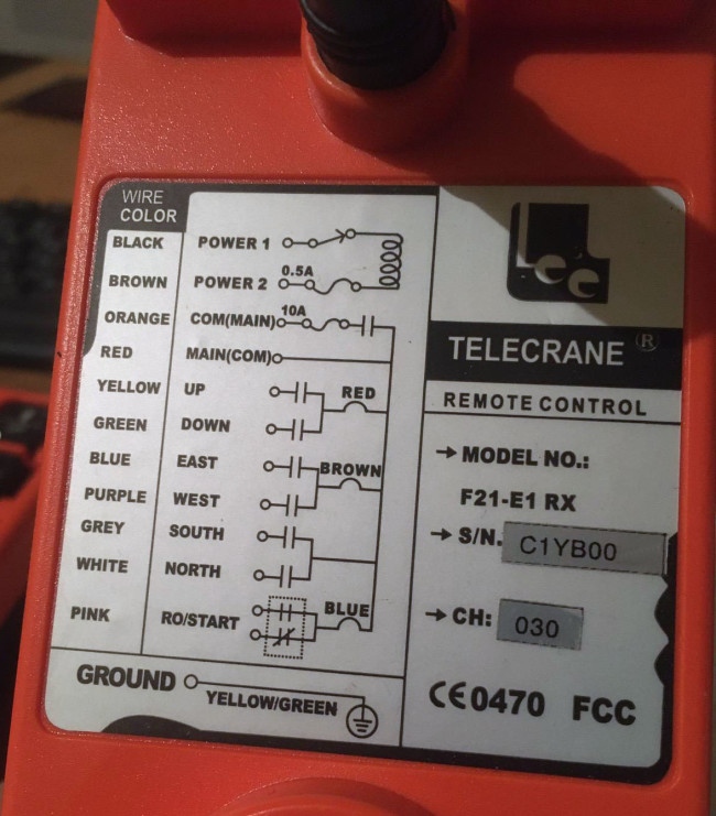
Figure 2 shows the remote control unit from China. It has a lot more buttons than are actually necessary. Up and Down would have been sufficient, but let’s not look a gift horse in the mouth. There must be some sort of electronics inside, since the ready-made cable has a lot of wires and even more buttons. This presumption turns out to be right. From the photo in Figure 3, which does not convey a lot of information, you can see that there are relays inside the box.
for the ready-made cable. It didn’t help much.
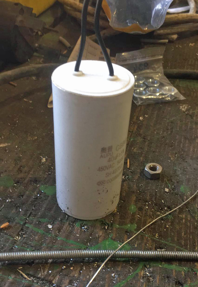
Radi did his best and sent me yet another photo with the somewhat cryptic wiring diagram of the internal terminals (Figure 4). He also sent a photo of the motor capacitor (Figure 5) he had acquired as a replacement for the somewhat outdated component on the hoist motor. That sums up the initial situation. From all this, can you determine whether Radi’s circuit design would work?
For me, it was not really enough information. After a phone call with a number of questions from me, it turned out that the motor was a permanent split capacitor induction motor. This means that the motor has two windings with a centre tap, with one winding connected directly to the AC mains and the other connected through a capacitor, and the direction of rotation can be changed by swapping the connections. The two small circles at the very top of Radi’s diagram with a wire between them are supposed to represent a limit switch. There is also a terminal for connecting the PE conductor to the case. Armed with this information, I was at least able to get started.
Circuit Versions
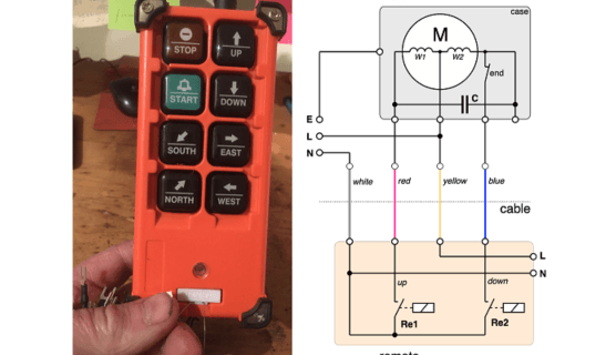
To better understand what my friend had in mind with his diagram, I started by drawing a clean version and then modified the circuit so that it could work in theory. This led to the diagram in Figure 6. As you can see, Radi was not that far off the mark. The only thing he hadn’t fully included was the limit switch in the motor. The L and N terminals of the remote control unit are for powering its inner circuitry, so that the relays can be energised when the buttons are pushed. I sent him my clean diagram and thought that the problem had been solved.
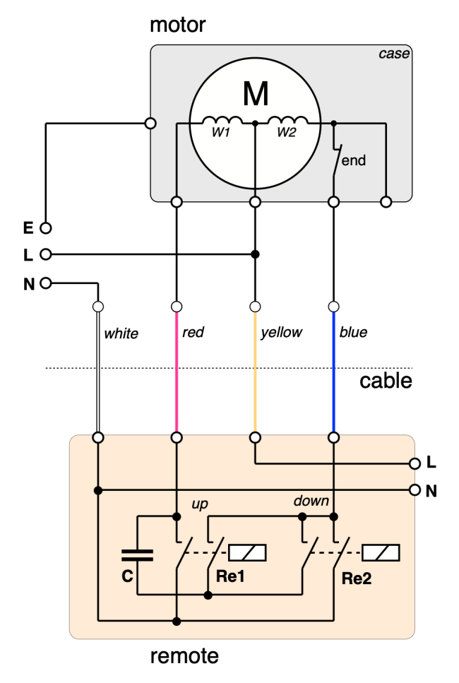
switch so that the motor switches off nicely at the end point.
As so often happens, I couldn’t get the circuit out of my mind. A difficulty with the solution I found is that the thick, bulky capacitor has to be attached to the slim remote control unit somehow. In addition, I remembered that a few decades ago there was an hours-long discussion in the Elektor editorial office about a rather simple circuit that was nevertheless special. Its five possible logical states were too much for my mental capacity when I tried to juggle with them. “Maybe that’s also the case here,” I thought to myself. This simple circuit, consisting of a motor with two windings, a capacitor, a cable with four wires and two relays with double contacts, was also a situation with five elements, making it not especially intuitive.
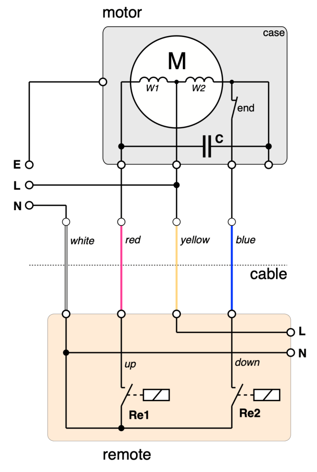
relay, and the capacitor goes back to the motor.
So, I sat down at the PC and fiddled with the circuit. Eventually, the light dawned and I suddenly saw that the dual contacts were actually not necessary. And there was a way to position the capacitor with the motor, where there was plenty of room in the housing. The result of these considerations is shown in Figure 7. It’s amazing how simple a solution can be once you have discovered it. So, I sent another email to Radi with the circuit in Figure 7, and called him to make sure I received a compliment for my clever solution.
(220171-01)
Questions or Comments?
Do you have any technical questions or comments about this article? Contact the editorial team at editor@elektor.com.
About the Author
Dr Thomas Scherer was a member of the Elektor editorial team for several years in the 1980s and has remained true to Elektor ever since. He loves to work on all sorts of electronics and has already written and edited many articles for Elektor.
Discussion (2 comments)