
USB Measurement Adapter: Testing Current and Signal Quality of USB Ports
on

When peripherals connected to a PC don't function or behave erratically, a thorough fault analysis of the USB port — beyond simple replugging or trying different PCs — often proves more revealing. The compact adapter introduced here allows you to insert an oscilloscope probe into the USB connection. This enables both current measurement and visualization of USB communication.
This article presents a compact, practical tool for measurements on USB 2.0 connections. Key features include:
- Static and dynamic measurement of the supply current for connected devices.
- Peripherals can be powered directly via the measurement adapter.
- Straightforward signal quality measurement of high-speed data lines.
- Two LEDs indicate the presence of a 5-V supply from both the PC and the peripheral device.

Circuit Description
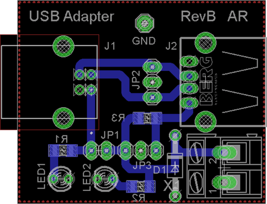
Figure 1 shows the relatively simple circuit, and Figure 2 depicts the compact layout of the adapter PCB, with layout files available online. The populated board in Figure 3 is missing diode D1. The PC connects to J1, a USB type B socket, using a USB-A-to-USB-B cable. The peripheral device connects to J2, a USB type A socket.
Current flow is detected as a voltage drop across the shunt resistor R3 via connector JP3. Static current measurements can be taken using a multimeter (typically in the millivolt range). For detecting rapid current changes, an oscilloscope should be connected to JP3 — ideally with a dedicated current probe. Two variants of such probes, enabling even galvanically isolated measurements of fast signals, have been detailed previously in Elektor (in 9-10/2016 and 11-12/2020).

The pinout of connector JP3 pinout allows direct attachment of these probes. Figure 4 shows the USB measurement adapter with the Current Probe 2.0 connected. Figure 5 illustrates the current profile of a USB Wi-Fi dongle that frequently draws high currents, often causing weaker 5-V plug-in power supplies to shut down.

Jumper JP1 allows for disconnecting the 5-V power line between the host (J1) and the peripheral (J2). In such cases, external power can be supplied to the peripheral through connector X1 — ideal when the peripheral’s current demand exceeds what the PC’s USB port can deliver. USB 2.0 ports are limited to 500 mA, which may already cause instability in some peripherals.

Zener diode D1 not only limits overvoltage (possibly by sacrificing itself) but also offers reverse polarity protection through its antiparallel diode. However, this is only a basic, temporary protection measure. Special care must be taken when connecting a lab power supply to ensure its output voltage remains below D1’s Zener voltage. LED1 and LED2 indicate the presence of 5-V power on the host and device sides, respectively.

differential probe connected.
Data Signals
To evaluate data signals and their integrity, a high-speed oscilloscope with a suitable probe can be connected to JP2. A compatible active, differential high-speed probe has also been described previously in Elektor. Figure 6 shows this probe attached to the USB measurement adapter. Figure 7 displays the observed data signals on a 350-MHz oscilloscope.

Naturally, the USB measurement adapter is not limited to USB 2.0; it can also be used to analyze slower peripherals, supporting USB 1.0 and 1.1 signals. The author still has a limited number of unpopulated boards available.

Editor's Note: This complete article (240175-01) appears in the Elektor Circuit Specail 2025.
Questions About the USB Measurement Adapter?
If you have any questions about the USB measurement adapter or comments about this article, email the author at alfred_rosenkraenzer@gmx.de or contact Elektor at editor@elektor.com.


Discussion (1 comment)