Power MOSFETs are ideal for controlling large loads from an Arduino or Raspberry Pi. Placing the MOSFET in the high side is often preferable but demands very high gate voltages — much higher than a microcontroller can deliver. Discover why n-channel MOSFETs are preferable to p-channel devices, and how to control them using a MOSFET driver.
When building an application with a microcontroller, you’ll want to control something at some point. This may be a device requiring minimal current, such as an LED, or something demanding a little more power, such as a DC motor. Most beginners quickly learn that devices, such as an Arduino or Raspberry Pi, cannot drive heavy loads directly. In such cases, a ‘driver’ is needed, a circuit that can accept the control signal from the microcontroller but has enough power to drive the desired load. MOSFETs are perfect in many cases, accepting a simple voltage at their input (gate) that allows a larger current to be controlled via their drain-source pins. However, there are times when the MOSFET itself also needs a driver. Let’s quickly review the role of MOSFETs as saturated switches before exploring how MOSFET drivers work.
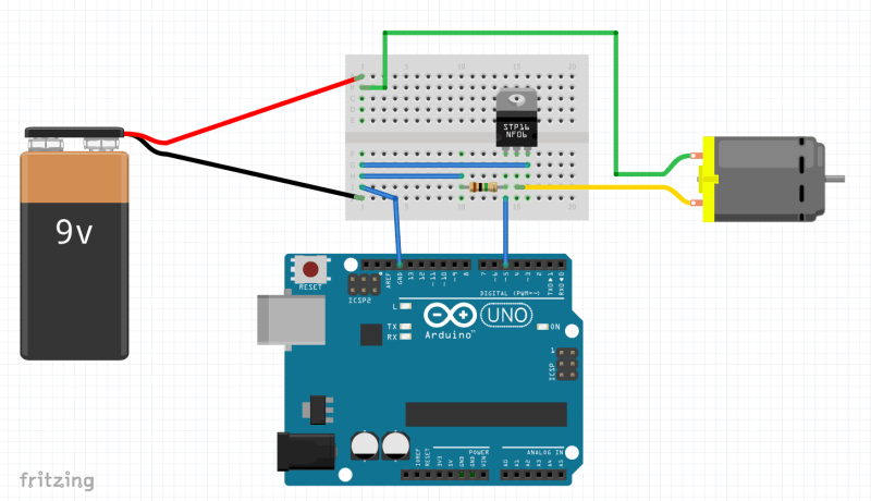
A MOSFET enables boards, such as an Arduino, to control large loads,
such as a DC motor.
Low-Side n-Channel MOSFETs for Switching
MOSFETs, specifically enhancement-mode MOSFETs, come in two types: n-channel and p-channel. N-channel MOSFETs require a higher voltage on their gate than the voltage on the source to turn on. The voltage at which this occurs is the threshold voltage, Vth. Pull out any n-channel MOSFET datasheet, and you’ll quickly find this value. For example, the Toshiba SSM3K56FS, a small high-speed switching device, gives Vth as between 0.4 V and 1.0 V when the drain-source voltage (VDS) is 3.0 V and for a drain current (ID) of 1 mA.
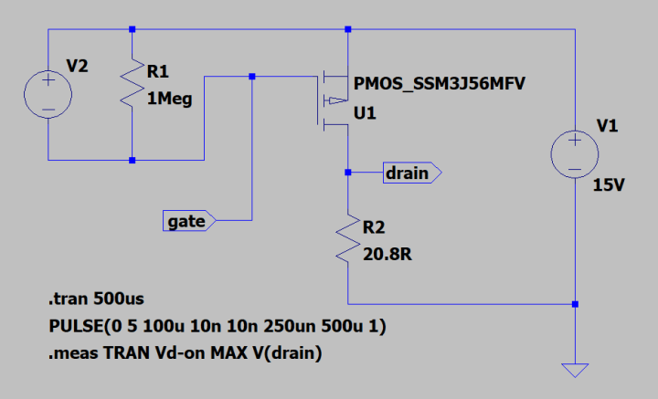
Such MOSFETs can be used as low-side switches, meaning they are placed between the load and the circuit ground in a simple low-voltage DC application. Thus, we can use a 5 V Arduino output pin connected to the gate of an SSM3K56FS, connect the source to the ground, and attach a motor between a 15V supply and the MOSFET’s drain. A resistor (1 MΩ) between the gate and the ground ensures that the MOSFET remains off should the control signal from the Arduino become detached.
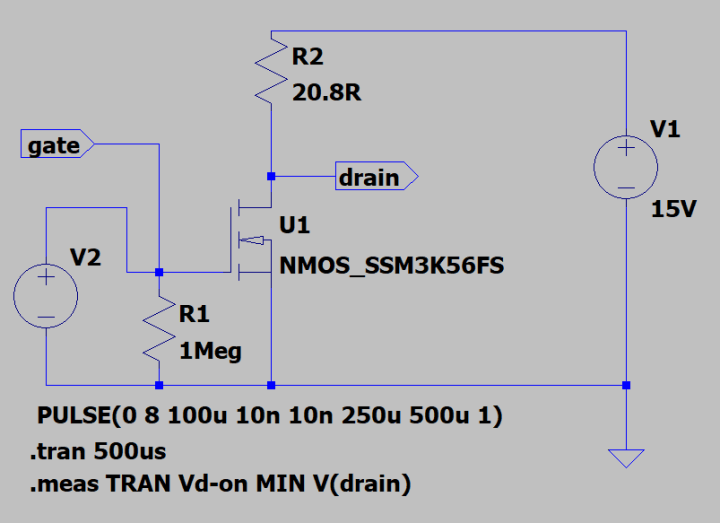
To demonstrate this, the circuit has been simulated in LTspice. V2 emulates the 5 V output from an Arduino I/O pin, while R2 is used as the load instead of a motor (we’ll ignore the difference between a resistive and inductive load). V1 is the 15 V supply.
Using a MOSFET as a low-side switch — an LTspice simulation.
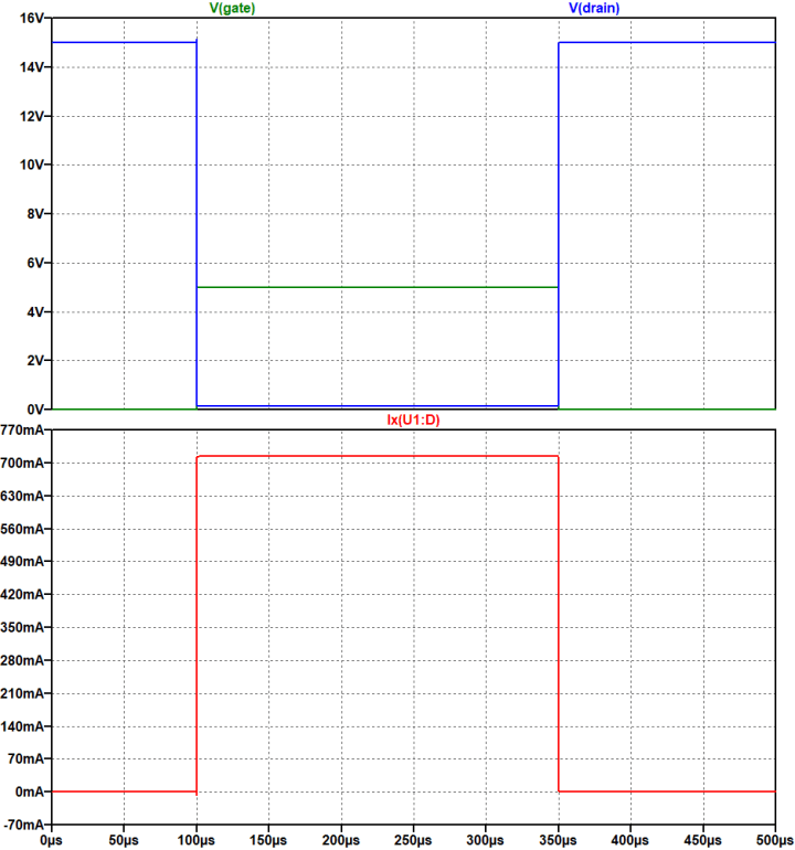
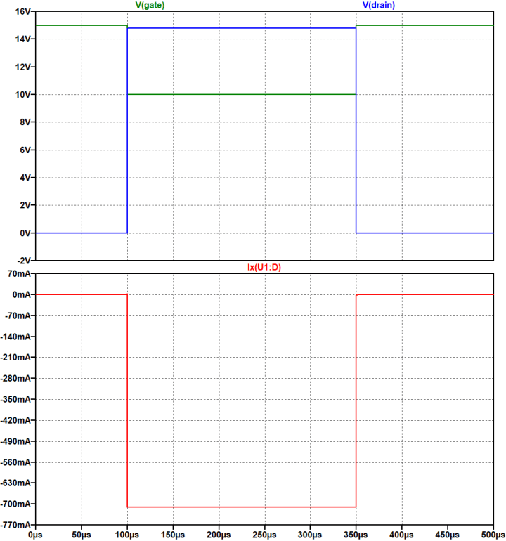
The signals show that the current flowing through the MOSFET is around 720 mA when 5 V is applied to the gate, below the maximum of 800 mA allowed.
With an Arduino supplying 5 V to the MOSFET gate the switch turns on,
delivering power to the load.
There is a further point to consider when reading the datasheet. Referring again to the SSM3K56FS, the reader will notice that the on-resistance value, RDS(ON), is dependent on VGS. For example, at a VGS of 1.5 V, RDS(ON) is 840 mΩ, while at 4.5 V, it is just 235 mΩ. The difference here is, admittedly, slight. When driving a motor, you’re unlikely to notice much difference between an Arduino driving the gate at 5 V and a Raspberry Pi driving it at 3.3 V.
However, if you’ve selected the MOSFET based upon its superior low on-resistance, it is important to remember that this is only achieved at the higher gate voltage given. According to the datasheet, the maximum allowable gate-source voltage, GGSS, is ±8 V, so plenty of headroom is available. This is important because power is lost in the MOSFET, and the resultant heat it has to dissipate will be higher when RDS(ON) is larger.
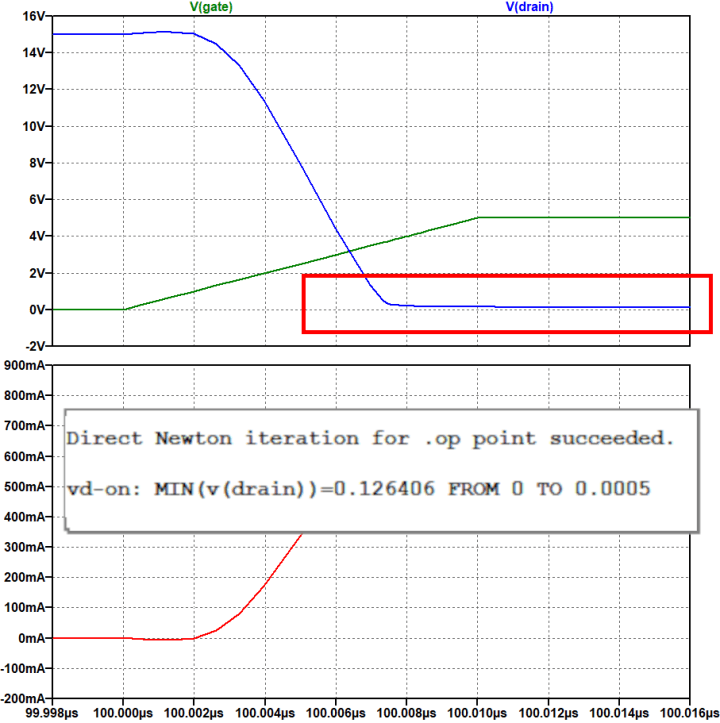
There is also a small disadvantage with low-side switching. Because the MOSFET’s on-resistance is on the low side between the load and ground, the load (and the MOSFET drain pin) floats slightly above ground. In our example, the drain sits at 0.126 V.
Because the MOSFET is in the low side, the load is not directly connected
to the ground of the application.
To complete the analysis, we should note that the power dissipated in the MOSFET is around 90 mW (715 mA at 0.126 V). This is comfortably inside the 150 mW defined in the datasheet. For a motor, this ground lift is of little consequence. However, if you wish to measure the current flowing through the motor using a small resistor, you’ll need a differential measurement rather than measuring with reference to ground.
If the load is a device like an Arduino, there is an additional issue as the Arduino’s ground will no longer be the same as the ground of the rest of the application. In fact, it will vary as the load changes. As a result, there is a risk of malfunction due to its ground and the ground of other circuits being different.
Additionally, because the load is permanently connected to the supply, electrons can find their way via other paths, such as I/O pins, through the microcontroller to ground, even when the MOSFET is off. Thus, the Arduino may still have enough power to be operational. Worst case, it may be sitting in an undefined brown-out state performing all sorts of strange actions.
In such cases, high-side switching should be considered.
High-Side p-Channel MOSFETs for Switching
If we exchange the n-channel MOSFET for a p-channel device, we can place the load between the MOSFET and ground. The source of the MOSFET is connected to the load’s power supply, and the load is connected to the drain. The complementary device to the n-channel MOSFET mentioned before is the Toshiba SSM3J56MFV. However, we immediately hit an issue.
A p-channel MOSFET can be used in the high side. However, this requires that the gate
be pulled down from the supply voltage, something that exceeds
the limits of an Arduino I/O pin.
Looking at the datasheet, we notice that Vth is given as -0.3 V to -1.0 V (for VDS -3.0 V and ID -1 mA). This means that the gate needs to be around 1.0 V lower than the source to start turning on. Sticking with our previous example using a 15 V supply for the motor, the gate needs to attain 14 V to start turning the MOSFET on. This is obviously an issue for an Arduino or Raspberry Pi with their 5 V and 3.3 V I/O pins, meaning an extra MOSFET or transistor is required to pull the gate down towards ground.
There is another issue, too. According to the data provided, the on-resistance at this gate voltage is around 4000 mΩ. To get the on-resistance down to its lowest level of 390 mΩ, the gate voltage must be -4.5 V. Even so, this is still 155 mΩ more than the complementary n-channel MOSFET we saw earlier and highlights another issue with p-channel MOSFETs – their higher (by comparison) RDS(ON).
Assuming there was a way for the Arduino to shift the gate voltage by -5 V, the p-channel high-side switch would respond as follows:
Pulling the gate to 5V below the supply turns on the switch, powering the load.
The issue is how to interface this with an Arduino or Raspberry Pi.
Examining the plot in detail, it can be seen that, when on, the source voltage reaches 14.79 V, around 0.21 V below the 15 V supply. Again, with around 715 mA flowing, this means the MOSFET is dissipating 150 mW, right at the limit of the device.
So, although p-channel MOSFETs are easier to make, n-channel MOSFETs provide a lower on-resistance for the same size. It is clear that, if possible, we’d be better off using an n-channel device in the high side.
However, as we have seen, to turn on an n-channel MOSFET, we need to set the gate voltage above that of the source. If we place the n-channel MOSFET in the high side, the source and drain have almost the same voltage when it is switched on, so the gate will need to be pushed to several volts above the level of the supply of the application.
Using Drivers with n-Channel MOSFETs as High-Side Switches
This is where MOSFET drivers come in. These clever little devices accept a low voltage control signal at their input and convert it to the voltage required to push the gate above the MOSFET’s source pin level. The higher voltage is generated using a ‘bootstrap’ circuit that utilizes a charge pump to push the gate voltage higher than the source voltage used in the application. While this adds extra cost and complexity to a circuit, designers benefit from the significantly more comprehensive range of low on-resistance, high-current capable n-channel power MOSFETs devices on offer.
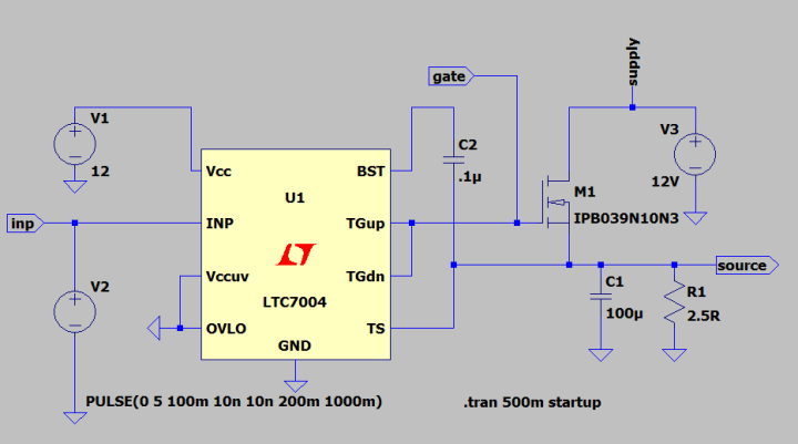
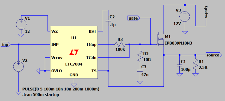
An excellent example of a MOSFET driver for this approach is the LTC7004 from Analog Devices (previously Linear Technology). This 10-pin device, of which only nine pins are used, only requires a capacitor in addition to the chosen MOSFET to operate as a switch. The input pin, INP, accepts CMOS level input signals up to 15 V. A power supply of between 3.5 V and 15 V is also required at the VCC pin. With a 0.1µF capacitor placed between the bootstrap pin BST and the top (high side) source pin TS, the LTC7004 can follow a MOSFET’s source voltage of up to 60 V. The device generates a gate voltage of 12 V above the source voltage. It also includes overvoltage and undervoltage lockouts to ensure correct operation.
The LTC7004 allows a microcontroller to control an n-channel MOSFET used as
a high-side switch by generating the control voltage required for the gate.
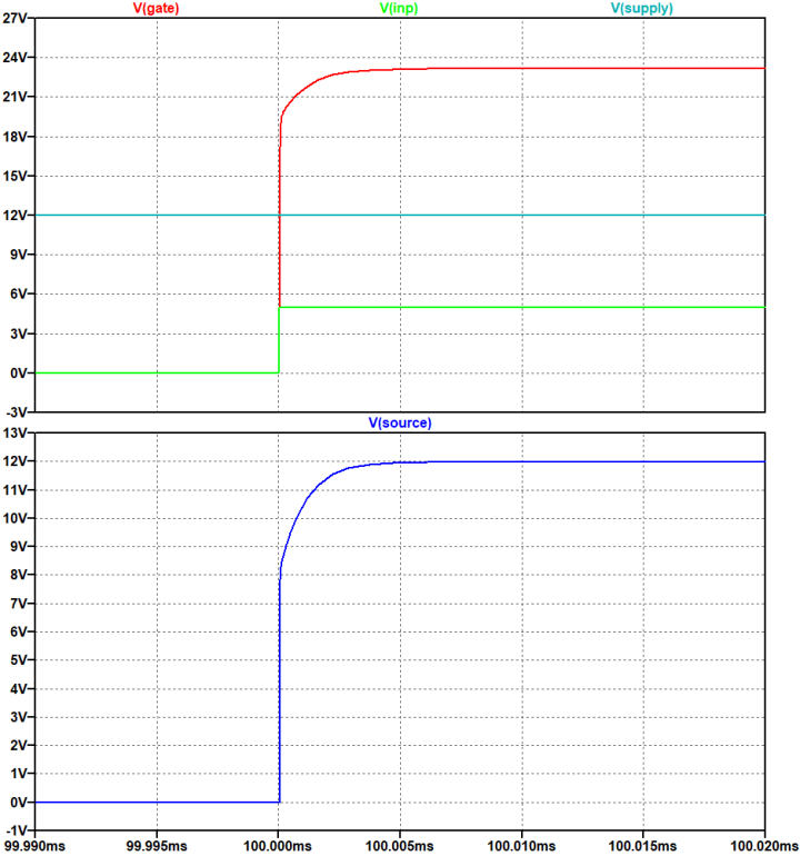
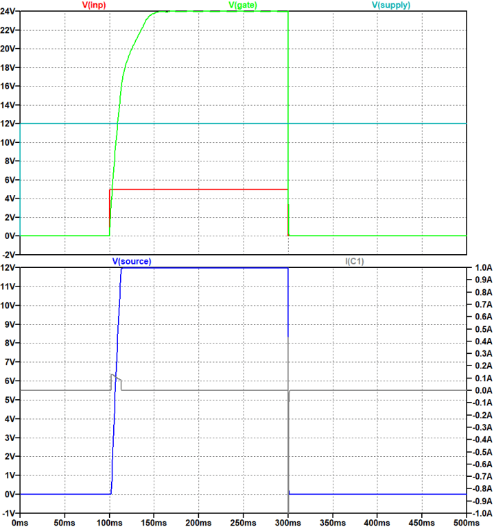
Using the 5 V I/O pin of an Arduino to control the circuit, you can see how the MOSFET driver quickly pushes the gate from 0 V to 24 V, 12 V above the load’s supply.
A 5V I/O signal from an Arduino results in the MOSFET gate
being pushedto 12 V above the load's supply voltage. This
ensures a fast and clean turn-on for the load.
To minimize losses in the MOSFET during switching, it is typically preferable to switch as quickly as possible. This is typically less of an issue in applications that are only occasionally turned on and off but much more critical in high-speed switching applications such as power converters (e.g., a buck converter). The LTC7004 provides a minimum rise/fall time of 13 ns and maximums of 90 ns (rise) and 40 ns (fall).
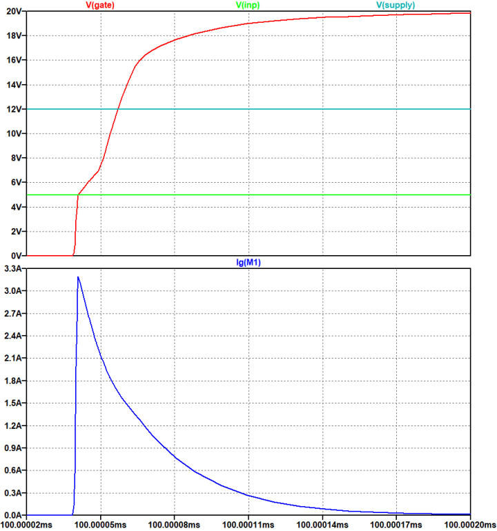
Another point to note is the current required by the gate of MOSFETs designed for power applications. The capacitance seen at the gate (known as Ciss) for the Infineon IPB039N10N3 used in this example can be more than 8400 pF. Zooming in on the switch-on point, it can be seen that the gate current reaches a peak of around 3.2 A. This is not unusual for power MOSFETs switching quickly and another reason why a microcontroller alone is not suited to switching them, even in low-side applications.
It is not unusual for power MOSFETs to require several amperes
at their gate during high-speed switching.
While turning the MOSFET on as hard and fast as possible is preferable to move it quickly from its off-state to its lowest resistance on-state, this can also cause issues in some applications. For example, if the MOSFET is powering a large capacitive load, the in-rush current at turn-on could be significant. MOSFET drivers like the LTC7400 provide two pins to control the gate, one for turn-on (TGUP) and one for turn-off (TGDN). This allows the turn-on and turn-off rates to be defined separately. Adding a small RC network (100 kΩ/47 nF) to the TGUP output makes it possible to slow down the turn-on rate and limit the in-rush current. An additional 10 Ω resistor helps to limit any oscillations. If the turn-off rate needs to be adjusted, a resistor can be added to the TGDN path.
Thanks to separate turn-on and turn-off pins, the switching speed of the
rising and falling edges can be controlled.
The surge current into the capacitive load is now reduced to around 180 mA and the voltage at the load ramps at around 2 V/ms.
The voltage applied to the capacitive load now rises at around 2 V/ms,
limiting the in-rush current to around 180 mA.
MOSFET Drivers Simplify the Construction of High-Side Switches
Power MOSFETs are ideal for controlling large loads, such as motors, from microcontroller-based platforms such as Arduino and Raspberry Pi. However, because of their better overall performance and lower RDS(ON), the choice of n-channel MOSFETs is much broader than the p-channel MOSFET offering.
If you wish to place the switch in the high side of your control circuit, the voltage applied to the n-channel MOSFET gate will need to be higher than the voltage at the source. Furthermore, power MOSFETs require significant current at the gate to switch quickly from being off to their lowest on-resistance, which is needed to minimize power dissipation in the MOSFET. MOSFET drivers, such as the LTC7004, resolve this issue by generating the gate voltage and current required to deliver a clean, fast turn-on in response to the control signal provided by your chosen microcontroller development board.
Elektor Magazine has been one of the leading sources of information on electronics for engineers, designers, start-ups and companies for 65 years. Our magazine is powered by an active community of electronics engineers – from students to professionals – who are passionate about designing and sharing innovative ideas.
For them, we publish hundreds of items a year, in formats such as articles, videos, webinars, and other learning formats. Our mission is to share knowledge in every possible way and inspire readers with the latest developments within the electrical engineering sector.
Thank you for your vote!
Leave further comments in the fields below.
Thank you for your vote!
If you wish to leave a comment with your rating, please first use the login below. If not, just close this window.


Discussion (9 comments)