
9-Channel Relay Control Board with PC Interface (130549)
Switch up to 9 loads by a simple button press or by sending a command over the serial port. 2500 W mar per channel, NO & NC contacts.
Update regarding MOD1
The BoB-FT232R used in this project is unfortunately no longer available. However, it can be replaced by the FT231X BoB and a few modifications:- Remove D2 from relay main board
- Remove C5 from relay main board
- Connect FT231X K3 pin 2 (or K2 pin 4) to R4 on relay main board
- Connect FT231X K3 pin 3 (or K2 pin 5) to R3 on relay main board
- Connect FT231X K2 pin 1 (or K3 pin 9) to GND on relay main board
For correct operation the relay main board must be powered through K1 and the FT231X must be powered over USB.
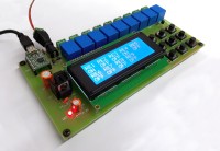
9 Channel Relay Control Board with PC Interface
Sometimes is it necessary to control or switch the appliances, light up or switch off light from some areas or switching MIC or audio in conference. This simple board will help out along with a simple PC interface with USB UART. In Movie Theater, it’s necessary to switch ON the lights in beginning, intermission and at the end of movie this simple and low cost solution will perfectly be useful for this job, where the operator can manually switch or PC can automatically trigger the lights.
This relay board has a wide range of applications in the automation sector. The devices or peripherals connected to the relays can be controlled via PC software.
Applications:
- Producing alarms on site as per criteria set by PC software.
- Controlling lights, fans and other appliances for home & office automation automatically by PC software and by direct user command settings on the PC only.
- Controlling climate control devices like air-purifier, humidifier, heater, AC as per criteria via PC software.
- Controlling all power points of a factory/production plant from control room, can timely be triggered, for e.g. only required area of lights can be kept ON and switching all the other off in Lunch time to saving electricity.
- Controlling climate control devices at poultry farm & similar places where human error can lead to big loss.
In short this board can be used everywhere, any devices, any peripherals, any appliances etc. required to be controlled from PC and manually.
Features:
- 9 Channels of relay units
- On board Elektor serial to USB BOB for easy PC interface
- 9 indusial switches for manual operation
- 20X4 LCD for displaying all 9 relay current status simultaneously.
- Powered from12V/1.5A DC adapter.
- 3 way terminal blocks for each relay connection, providing NO & NC both connections for each relay.
- Works with any serial software utility with simple code or relay ON/OFF.
The system consists of hardware and software, the heart of the system is IC2 PIC18F45K22-E/P which makes all the decisions with acknowledgement from PC USB UART and manual switches. The simple command for making each relay ON/OFF can be send through PC using serial software utility. LCD on board will help in displaying relay status.
Hardware:
- K1: 12VDC connection jack for adapter.
- K3-K11: Relay output connector
- K2: PIC ISCP connector
Circuit Description:
The simple hardware is designed using PIC MCU IC2 PIC18F45K22-E/P, which controls the relay through IC3 (ULN2803) and transistor T2. IC3 consists of eight NPN Darlington pairs that feature high-voltage outputs with common-cathode clamp diodes for switching inductive loads. The MCU also drives a 20X4 LCD to display the status of each relay. Transistor T2 is used to control the LCD backlight. Trimmer P1 is used to adjust the contrast of the LCD.
BOB1 is the Elektor RS232 to USB module used to enable PC connectivity for controlling the unit through PC for MCU UART.
Switch S1 to S9 are indusial switches for each relay, 12mm big push switches are used for easy operation. All switches are connected in keyboard matrix row and columns. RN1 10k resistor network is used as pull-up resistor for key matrix MCU pins.
12VDC can be connected to board through barrel jack K1, this 12V is applied to all the relay as +VE. IC3 is also powered from +VE line. This +VE is also used by IC1 MC7805 after diode D1. The +5V output from regulator IC1 is used for rest of the circuit. LED1 indicates power ON of board.
Software:
The MCU software is written in CCS C compiler for PIC18F45K22.The MCU is operates at 16MHz by internal oscillator, eliminating need or an external crystal.
At power on all relays are kept off. After unit is switched ON it will display the Project Name & Number for 3 seconds. Followed by the main screen where all the relay status are displayed simultaneously.
Then it enters the main loop.
Here it checks for two operations.
- It checks if any command is received via UART then it will update the display accordingly
- It checks keyboard for any key press & does its operation. Also update relay status on the LCD display and sends to UART.
Two interrupts are used, one for UART and the other for timer1 overflow. The MCU internal UART hardware is used to receive commands & sending status. The UART receive interrupt is enabled to avoid any data loss while receiving command from PC. The UART is configured to operate at 9600 baud rate. As soon as it receives any command. It checks the command & changes the relay status as per the command received and also updates relay status on the LCD as well as sends to UART.
The timer1 overflow rate is kept of 1mS. This is to read the 3 x 3 matrix keyboard. One more function is added in timer1 ISR, is to switch OFF the LCD backlight after 5 minutes for power saving. As soon as any key is pressed or any command is received the MCU switches the backlight of LCD ON using transistor T1.
Following are the UART commands:
$RLY1ON& -----Relay 1 “ON”
$RLY1OF& ----- Relay 1 “OFF”
$RLY2ON& -----Relay 2 “ON”
$RLY2OF& ----- Relay 2 “OFF”
$RLY3ON& -----Relay 3 “ON”
$RLY3OF& ----- Relay 3 “OFF”
$RLY4ON& -----Relay 4 “ON”
$RLY4OF& ----- Relay 4 “OFF”
$RLY5ON& -----Relay 5 “ON”
$RLY5OF& ----- Relay 5 “OFF”
$RLY6ON& -----Relay 6 “ON”
$RLY6OF& ----- Relay 6 “OFF”
$RLY7ON& -----Relay 7 “ON”
$RLY7OF& ----- Relay 7 “OFF”
$RLY8ON& -----Relay 8 “ON”
$RLY8OF& ----- Relay 8 “OFF”
$RLY9ON& -----Relay 9 “ON”
$RLY9OF& ----- Relay 9 “OFF”
Building Prototype:
The simple single sided PCB is designed; solder the components as per BOM list with IC base for the IC2 and IC3. Don’t forget to connect HS1 heat sink to IC1 MC7805.
Testing Prototype:
- Connect the 12VDC to connector K1.
- Connect the BOB1 USB to PC USB Port and start the serial software on PC or
- Download and install the serial utility like MU terminal.
- Start the MU Terminal and set below setting in RS232 connection
- COMM. Port --- set available com port of BOB Module from drop down menu
- Baud Rate: 9600
- Data Bits: 8
- Parity : None
- Stop Bits: 1
- Click on “COMM OPEN” button.
- Switch ON the Power supply.
- LCD shows the welcome screens of the project, later status of all relays are displayed on screen. (initially all are “OFF” at power ON)
- Same time MU Terminal receives the signal from MCU and displayed welcome screen on Terminal Send/Receive block along with information of relay On and OFF codes.
- Press the respective switch to switch ON and OFF respective relay, every press will toggle the relay status and same will be updated on LCD screen.
- In MU Terminal delete all text from “Text Terminal” block and type the command/code for switching relays ON or OFF.
Want to build a project?
Bring your design to life with the Elektor PCB Service, powered by Eurocircuits. Upload the project files and order professionally manufactured PCBs or assembled boards through a proven European production platform.
Supporting KiCad, Eagle, Gerber, and ODB++ formats, the service is suitable for everything from prototypes and validation builds to series production and volume manufacturing.
Made in Europe. Fast. Reliable. Professional.
Discussion (2 comments)