FT232R USB/Serial Bridge/BOB
Microcontrollers
Continue reading this Elektor article?
- Unlimited access to online Member Only articles
- 3 new editions Elektor Magazine (digital)
- More than 5000 Gerber files
- 20% member discount on e-books (at elektor.com)
- 10% member discount on Products (at elektor.com)
Stops Automatically.
What is Members Only
Elektor is committed to providing high-quality content on electronics, catering to tens of thousands of paying members. As part of this commitment, Elektor has launched Premium, an initiative that offers exclusive online articles to members sometimes even before they appear in the magazine.
Every day, members can access in-depth articles that showcase the best of Elektor's premium content.
This initiative aims to reward members with early access. Once logged in, members can easily enjoy this exclusive content and engage in discussions about featured projects. While Premium adds to the existing resources available, Elektor will continue to provide a wealth of free information.
Join the Elektor community today to take advantage of Premium and other benefits!
Materials
Extra info / Update
Supplementary information
Issued: October 10, 2011.
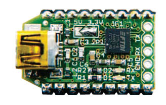
The metallised semicircles at the edge of the PCB is a feature of the BOB-FT232R. This advanced technology allows the vertical SIL connectors (supplied with the module) to be soldered, as well as the module itself to be soldered directly in "piggyback" fashion onto a board of your own design. To assist you with the design of a suitable footprint, a library for Eagle CAD software (http://www.cadsoftusa.com/) is provided free of charge on this web page.
To facilitate the soldering of the vertical connectors customers are advised to use a piece of dense foam (like antistatic foam used to hold through-hole components) or a breadboard, or a carrier PCB (if correctly drilled).
The 3.3 V or 5 V I/O level voltage MUST be defined. This is done with a drop of solder tin on the relevant SMD jumper position on the board (JP1). Be careful not to solder all pads together as that will damage the board.
Component list
Resistors
R1,R2 = 270Ohm (0603)
Capacitors
C1, C2 = 47pF (0603)
C3 = 10nF (0603)
C4 = 4.7?F 6.3V (0603)
C5, C6 = 100nF (0603)
Inductors
L1, L2 = ferrite bead >30Ohm @ 100 MHz / 1.5 A (0603)
Semiconductors
IC1 = FT232RQ
D1 (TX) = LED, green (0603)
D2 (RX) = LED, red (0603)
Miscellaneous
K1 = USB mini-B connector
18-pin (2x9) pinheader, right angled Pinheader
Discussion (0 comments)