
Arduino Controlled Wack A Mole
Arduino Controlled Wack A mole
Arduino Controlled Wack A mole
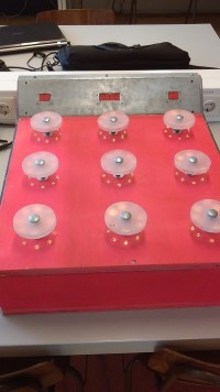
The pcb is composed of 4 parts, in the first section (the main board), all the data processed from the Arduino, and is therefore the most of the rest. The rest of the parts are the PCBs in which the 7-segment displays come on, so that they are in a fixed place, the data lines need not be soldered directly to the displays and to be able to mount the display on the housing. The total PCB size is 117mm x 126mm. The mainboard consists of 47 components in total: • 4x 74HC595 shift registers; • 25 resistors. 10k 8x, 17x 100R; • two resistor networks. 10k SIL10 1x, 1x 10k SIL 6; • 8 transistors. 8x BC547; • 5 pin sockets. 9PIN 1x, 3x 8pin, 1x 5pin; • 4 pin headers. 10pin 1x, 2x 8pin, 1x6pin. The boards of the seven-segment displays include: • 8x seven segment displays. CC LED per segment; • 4 pin sockets. 4x 8pin. If you think the mainboard looks at you immediately see it has an L shape. This is designed so that all the PCBs to each other one rectangle to complete. This is especially useful when routing, because this design more than once can be put side by side without any loss of unnecessary buyer of the cutter plate. In this design has been chosen for four shift registers as they increase the outputs of the third outputs to 32 outputs. Of these, we use there are 32 outputs 25 and use them to drive a 25x8 LED matrix: 17 for the anodes of the LEDs, and 8 for the cathodes. For anodes, we have put a limiting resistor to limit the current to the LEDs. For the cathodes, we have placed a transistor and resistance at the base because the total current of a row is greater than 20mA. 20mA is the maximum allowable flow of a shift register. 8 go to the anodes of the 7-segment displays, and 9, going to the LEDs that represent the moles. Sitting in the matrix eight 7-segment displays one a 8x9 LED matrix. The LEDs are not on a PCB as they are too far apart on the housing to create a print that. Why are the LEDs on the enclosure itself. For the buttons of the moles there is a 9-pin pin socket on the mainboard with a SIL10 resistor network that acts as the pull-down resistors on the inputs. For the inputs: start, player 1, player 2, potentiometer and a sensor is used the same principle but with a 5-pin socket and a SIL5 resistor network. The sensor was eventually deleted, because the sensor came in too late. Because we thought that the sensor would come in on time, we had been milled to the print, so that it was too late to change the print on it
Want to build a project?
Bring your design to life with the Elektor PCB Service, powered by Eurocircuits. Upload the project files and order professionally manufactured PCBs or assembled boards through a proven European production platform.
Supporting KiCad, Eagle, Gerber, and ODB++ formats, the service is suitable for everything from prototypes and validation builds to series production and volume manufacturing.
Made in Europe. Fast. Reliable. Professional.
Discussion (1 comment)