
Voltage current calibrator 0 to +/- 10V, and 0 to 40mA 0.001%
Generate any accurate voltage 0 to +/-10V with 20uV step and 0 to 40mA 100nA for your design or for multimeter, oscilloscope calibration source
I bought a broken oscilloscope from EBay and in order to take full advantage of its features, it had to be calibrated in voltage and, in current. Normally requested calibration values are 1.000V or 10.000mA… but for this oscilloscope, specific voltage and current sources were needed: +/- 1.7694V and 20.253mA.
There are many calibrator solutions on the market but these devices are out of my budget or, did not have the required resolution.
So, the solution for me was to build a calibrator by myself.
Video link : https://youtu.be/i8ZxOXWNTnU
Specifications
Output voltage 0 to +/- 10V with 20uV resolution.
Current 0 to 40mA, resolution 100nA.
Accuracy 10ppm (10 parts per million) at 21°C which is 0.001% at 21°C.
Easy to calibrate by soft.
Power supply via USB. Battery option.
3.5”Color touch screen to avoid front panel buttons machining.
1 Schematic
There are 5 main blocks in my design: The power supply The voltage reference The DAC around the AD5791 The current generator The HMI, with its microcontroller
The power supply:
Power is supplied from an USB PSU providing at least 500mA. The 5V supplied is divided into two separate parts. One way feeds the HMI with the microcontroller. The other way feeds the DAC and voltage reference in +/- 15V, using an isolated up converter. The +/- 15V output is filtered and goes into two linear regulators, both regulators are low drop out voltage and low noise.
The voltage reference:
This is the most critical element in this circuit. If we need a reference voltage of 10.00000V at +/- 10uV, we want this forever but in the real world, it can’t be reach. The topic of voltage references is a science in itself, on the web there are dozens of articles and specialists who discuss this subject in order to push the limits of features such as: noise, stability in ppm / ° C in the short and long term, hysteresis, thermoelectric EMF, piezoelectric… In your favorite search engine let see the Rolls of voltage references: the LTZ1000 with a drift of 0.05ppm / ° C. Some authors have produced voltage references with amazing and beautiful PCBs with very low temperature coefficient resistor in oil filled metal housing. After testing three voltage references (LTC6655, ADR445, MAX6350ESA), I chose the MAX6350ESA from Maxim which I found to be more stable over time with 5V output. With both Op Amp U10A / B inside the AD8676 (Dual low noise, low offset drift voltage Op amp) +10.48V and - 10.48V are produced. The resistors R16, R17, R18, R19, R20 around the AD8676 are low temperature drift resistors (better than 2ppm / ° C).
The DAC around the AD5791
The chosen DAC is AD5791 for its 20-bit and for its linearity of 1ppm. This linearity feature simplifies the calibration: Only the 0V point and 10V point need to be adjusted. The 20-bit DAC1220 with 15ppm of linearity requires a correction table so I didn’t choose it. The schematic around the AD5791 uses the elements of the Analog device Eval board. The DAC receives the reference voltages of +10.48V and - 10.48V which produces a step of roughly 20uV. The output voltage Vout = ((+ Vref - (- Vref)) / 2e20 -1) x code –Vref Or, approximately Vout = 2 x code -10.48576 The calibrator output is software limited to +/- 10V. This gives a large capability to compensate the offset error at 0V
The precision current source
The four main components of the precision current source are U7 AD8276 instrument amplifier, Q1 PZT1222, U8 8677 and R10 100ohm. Q1 provides the current to the load. This current flows through the R10 (measurement resistor) and the relay and then, goes to the load under test to finally return to ground. The voltage on R10 terminal is measured by U8 and U7 is compared to the reference voltage supplied by the DAC AD5791. Output source current = VDAC / R10 or VDAC / 100 The current is limited to 40mA by the software to avoid voltage measurement drift in R10 due to thermal heating inside R10 and Q1. The temperature coefficient of resistance R10 is critical and must be as low as 0.2ppm / ° C. For this reason, the implantation of Q1 is as far as possible from R10 and of course from reference voltages.
The HMI with its microcontroller
This part is done by an ulcd35DT module from 4D system which integrates a 3.5 "resistive color touch screen and the microcontroller. The IDE is free and contains the touch button function libraries for this project. The code is a simplified form of C.
The GUI is made as follows:
Touch buttons and digits are images stored on the micro SD card. Each image has x,y coordinates on the touchscreen. When the screen is touched, an interrupt is generated to give which image has been touched and the dedicated action occurs.
Operation: the screen consists of a touch-sensitive encoder wheel and three buttons. The +/- buttons of the encoder wheels select the output value. The "sign" buttons reverse the sign of the output voltage. Inactive in current mode.The "000" button sets the output to 0V The "Volt / mA" button selects the current or voltage mode
2 Calibration
The calibrator needs to be aged before its calibration.
Voltage reference aging
As any reference voltage source, it has to be aged to improve long term stability. I chose 1000 hours at room temperature. After 41 days (1000 hours) over 1 week, the reference is stable at 4.99994V and the two references 10.50050 and -10.49867 are stable at +/- 10uV.
Calibration of the…calibrator
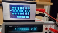
A minimum 6.5 digit multimeter is required. I used my Agilent 34410APressing and holding the "Sign" button for 8 seconds clear all calibration factors
Calibration in voltage mode:
Long press for 5 seconds on the "000" button to start the calibration. Press the “Volt/mA” button to interrupt the calibration sequence. Use the “+” and “-“buttons of the encoder wheels to obtain 0V +/- 15uV on the multimeter. Wait about 10 seconds to stabilize. Press "000": "cal stored" is displayed for 2 seconds then the encoder wheels display 10.00000. Using the encoder wheels, select the value necessary to generate 10.00000V +/- 15uV.
Calibration in current mode:
Long press for 5 seconds of the "000" button to start the calibration.
The encoder wheels display 00.0100mA. Using the “+”and ”-“ buttons on the encoder wheels, select the value necessary to generate 10uA +/- 100nA on the multimeter.
Press "000" : "cal stored" is displayed for 2 seconds then the encoder wheels display 30.0000. Using the encoder wheels, select the value necessary to generate 30mA +/- 100nA.
3 Other
Enclosure
The calibrator PCB with its display is designed to fit the Hammond Enclosure
Battery option
The calibrator PCB is designed to install a Chinese battery charger and discharger (ref DDO4CVSA) from Eletechsup manufacturer but it has not been used here finally because it heated too much.
Future improvement
Any temperature variation modifies the calibrator output accuracy. I put a thermal sensor (NTC) on the PCB at the back of the voltage reference. May be I will use this thermal sensor for correcting the drift of the reference voltage or may be I will ovenize the reference voltage area on PCB....
4 References
Long term characterization of voltage references from Hubert Halloin, Pierre Prat, and Julien Brossard https://arxiv.org/pdf/1312.5101.pdf
Current Sources & Voltage References from Linden T. Harrison
https://doc.xdevs.com/doc/_Metrology/Print%20Ver.%20-%20Current_Sources_and_V%20_Refs.pdf
https://xdevs.com/article/kx-ref/ for LTZ1000
AD5791 Eval board
https://www.analog.com/en/design-center/evaluation-hardware-and-software/evaluation-boards-kits/eval-ad5791.html
5 Improvements June 19th 2021
Version 1-3
Main Improvements
Voltage Drift
The drift can be due (not only) to the temperature variation and to the age of the component.
1) Aging More a reference source is old, more it is stable. To speed up the aging I did three up and down temperature cycles from -20°C to 20°C. After more than 1000 hours of power ON, I measured the output during 24 hours and the stability has become roughly around 2 ppm. See test results sheet. 2) Temperature coefficient The drift of the output voltage versus temperature (TEMPCO) is measured in ppm/volt. So, with a 10V output signal, 1 ppm gives 10 uV.
My lab temperature can be from 15°C to 25°C, not in one day of course, but, if the output has a TEMPCO of 2.5ppm/°C, the voltage output can change up to 250 uV in this temperature range.
I used a DIY thermal chamber with a temperature controller. I did a 5 hours temperature cycle from 15°C to 40°C. I got 1 ppm/°C. So, for 10 V output I got 9.999823 V at 42°C and 10.000062 V at 14°C. This gives 1 ppm/°C. See “with vs_without heater” excel files.
I wondered if I could do a better TEMPCO if I ovenized the reference. The goal was to heat the reference circuit to stabilize the temperature. I chose a set point at 55°C. So, I built a temperature controlled heater on little PCB and I glued it on the bottom side of the reference circuit of the calibrator. I put the calibrator in my thermal chamber, I did a 5 hours temperature cycle from 15°C to 40°C and I got a drift of the output voltage of 26 uV so this gives a TEMPCO less than 0.2ppm/°C. Five time better without heater!
New PCB
Correction of layout error, improvement of the output sense layout against external load.
Now internal is resistance: 0.016 Ohm. The maximum load is 5 mA to save accuracy.
Modification of reference circuit position to place a case surrounding the reference. I used my 3D printer to print the case.
Diagram
Correction of label errors. Added measure of reference temperature for alarm and warm up for the software and display. Output sense modifications.
Software
Added messages during calibration process
Added warm up and heater alarm messages
Added message “open loop” in mode current
Bug correction on tactile functionalities
6 Measurement and plots update July 08th,2021
Add noise plots measurement with PN9000 noise analyser instrument
- Calibrator_noise+10V.jpg- Calibrator_noise-10V.jpg
There are many calibrator solutions on the market but these devices are out of my budget or, did not have the required resolution.
So, the solution for me was to build a calibrator by myself.
Video link : https://youtu.be/i8ZxOXWNTnU
Specifications
Output voltage 0 to +/- 10V with 20uV resolution.
Current 0 to 40mA, resolution 100nA.
Accuracy 10ppm (10 parts per million) at 21°C which is 0.001% at 21°C.
Easy to calibrate by soft.
Power supply via USB. Battery option.
3.5”Color touch screen to avoid front panel buttons machining.
1 Schematic
There are 5 main blocks in my design: The power supply The voltage reference The DAC around the AD5791 The current generator The HMI, with its microcontroller
The power supply:
Power is supplied from an USB PSU providing at least 500mA. The 5V supplied is divided into two separate parts. One way feeds the HMI with the microcontroller. The other way feeds the DAC and voltage reference in +/- 15V, using an isolated up converter. The +/- 15V output is filtered and goes into two linear regulators, both regulators are low drop out voltage and low noise.
The voltage reference:
This is the most critical element in this circuit. If we need a reference voltage of 10.00000V at +/- 10uV, we want this forever but in the real world, it can’t be reach. The topic of voltage references is a science in itself, on the web there are dozens of articles and specialists who discuss this subject in order to push the limits of features such as: noise, stability in ppm / ° C in the short and long term, hysteresis, thermoelectric EMF, piezoelectric… In your favorite search engine let see the Rolls of voltage references: the LTZ1000 with a drift of 0.05ppm / ° C. Some authors have produced voltage references with amazing and beautiful PCBs with very low temperature coefficient resistor in oil filled metal housing. After testing three voltage references (LTC6655, ADR445, MAX6350ESA), I chose the MAX6350ESA from Maxim which I found to be more stable over time with 5V output. With both Op Amp U10A / B inside the AD8676 (Dual low noise, low offset drift voltage Op amp) +10.48V and - 10.48V are produced. The resistors R16, R17, R18, R19, R20 around the AD8676 are low temperature drift resistors (better than 2ppm / ° C).
The DAC around the AD5791
The chosen DAC is AD5791 for its 20-bit and for its linearity of 1ppm. This linearity feature simplifies the calibration: Only the 0V point and 10V point need to be adjusted. The 20-bit DAC1220 with 15ppm of linearity requires a correction table so I didn’t choose it. The schematic around the AD5791 uses the elements of the Analog device Eval board. The DAC receives the reference voltages of +10.48V and - 10.48V which produces a step of roughly 20uV. The output voltage Vout = ((+ Vref - (- Vref)) / 2e20 -1) x code –Vref Or, approximately Vout = 2 x code -10.48576 The calibrator output is software limited to +/- 10V. This gives a large capability to compensate the offset error at 0V
The precision current source
The four main components of the precision current source are U7 AD8276 instrument amplifier, Q1 PZT1222, U8 8677 and R10 100ohm. Q1 provides the current to the load. This current flows through the R10 (measurement resistor) and the relay and then, goes to the load under test to finally return to ground. The voltage on R10 terminal is measured by U8 and U7 is compared to the reference voltage supplied by the DAC AD5791. Output source current = VDAC / R10 or VDAC / 100 The current is limited to 40mA by the software to avoid voltage measurement drift in R10 due to thermal heating inside R10 and Q1. The temperature coefficient of resistance R10 is critical and must be as low as 0.2ppm / ° C. For this reason, the implantation of Q1 is as far as possible from R10 and of course from reference voltages.
The HMI with its microcontroller
This part is done by an ulcd35DT module from 4D system which integrates a 3.5 "resistive color touch screen and the microcontroller. The IDE is free and contains the touch button function libraries for this project. The code is a simplified form of C.
The GUI is made as follows:
Touch buttons and digits are images stored on the micro SD card. Each image has x,y coordinates on the touchscreen. When the screen is touched, an interrupt is generated to give which image has been touched and the dedicated action occurs.
Operation: the screen consists of a touch-sensitive encoder wheel and three buttons. The +/- buttons of the encoder wheels select the output value. The "sign" buttons reverse the sign of the output voltage. Inactive in current mode.The "000" button sets the output to 0V The "Volt / mA" button selects the current or voltage mode
2 Calibration
The calibrator needs to be aged before its calibration.
Voltage reference aging
As any reference voltage source, it has to be aged to improve long term stability. I chose 1000 hours at room temperature. After 41 days (1000 hours) over 1 week, the reference is stable at 4.99994V and the two references 10.50050 and -10.49867 are stable at +/- 10uV.
Calibration of the…calibrator
A minimum 6.5 digit multimeter is required. I used my Agilent 34410APressing and holding the "Sign" button for 8 seconds clear all calibration factors
Calibration in voltage mode:
Long press for 5 seconds on the "000" button to start the calibration. Press the “Volt/mA” button to interrupt the calibration sequence. Use the “+” and “-“buttons of the encoder wheels to obtain 0V +/- 15uV on the multimeter. Wait about 10 seconds to stabilize. Press "000": "cal stored" is displayed for 2 seconds then the encoder wheels display 10.00000. Using the encoder wheels, select the value necessary to generate 10.00000V +/- 15uV.
Calibration in current mode:
Long press for 5 seconds of the "000" button to start the calibration.
The encoder wheels display 00.0100mA. Using the “+”and ”-“ buttons on the encoder wheels, select the value necessary to generate 10uA +/- 100nA on the multimeter.
Press "000" : "cal stored" is displayed for 2 seconds then the encoder wheels display 30.0000. Using the encoder wheels, select the value necessary to generate 30mA +/- 100nA.
3 Other
Enclosure
The calibrator PCB with its display is designed to fit the Hammond Enclosure
Battery option
The calibrator PCB is designed to install a Chinese battery charger and discharger (ref DDO4CVSA) from Eletechsup manufacturer but it has not been used here finally because it heated too much.
Future improvement
Any temperature variation modifies the calibrator output accuracy. I put a thermal sensor (NTC) on the PCB at the back of the voltage reference. May be I will use this thermal sensor for correcting the drift of the reference voltage or may be I will ovenize the reference voltage area on PCB....
4 References
Long term characterization of voltage references from Hubert Halloin, Pierre Prat, and Julien Brossard https://arxiv.org/pdf/1312.5101.pdf
Current Sources & Voltage References from Linden T. Harrison
https://doc.xdevs.com/doc/_Metrology/Print%20Ver.%20-%20Current_Sources_and_V%20_Refs.pdf
https://xdevs.com/article/kx-ref/ for LTZ1000
AD5791 Eval board
https://www.analog.com/en/design-center/evaluation-hardware-and-software/evaluation-boards-kits/eval-ad5791.html
5 Improvements June 19th 2021
Version 1-3
Main Improvements
Voltage Drift
The drift can be due (not only) to the temperature variation and to the age of the component.
1) Aging More a reference source is old, more it is stable. To speed up the aging I did three up and down temperature cycles from -20°C to 20°C. After more than 1000 hours of power ON, I measured the output during 24 hours and the stability has become roughly around 2 ppm. See test results sheet. 2) Temperature coefficient The drift of the output voltage versus temperature (TEMPCO) is measured in ppm/volt. So, with a 10V output signal, 1 ppm gives 10 uV.
My lab temperature can be from 15°C to 25°C, not in one day of course, but, if the output has a TEMPCO of 2.5ppm/°C, the voltage output can change up to 250 uV in this temperature range.
I used a DIY thermal chamber with a temperature controller. I did a 5 hours temperature cycle from 15°C to 40°C. I got 1 ppm/°C. So, for 10 V output I got 9.999823 V at 42°C and 10.000062 V at 14°C. This gives 1 ppm/°C. See “with vs_without heater” excel files.
I wondered if I could do a better TEMPCO if I ovenized the reference. The goal was to heat the reference circuit to stabilize the temperature. I chose a set point at 55°C. So, I built a temperature controlled heater on little PCB and I glued it on the bottom side of the reference circuit of the calibrator. I put the calibrator in my thermal chamber, I did a 5 hours temperature cycle from 15°C to 40°C and I got a drift of the output voltage of 26 uV so this gives a TEMPCO less than 0.2ppm/°C. Five time better without heater!
New PCB
Correction of layout error, improvement of the output sense layout against external load.
Now internal is resistance: 0.016 Ohm. The maximum load is 5 mA to save accuracy.
Modification of reference circuit position to place a case surrounding the reference. I used my 3D printer to print the case.
Diagram
Correction of label errors. Added measure of reference temperature for alarm and warm up for the software and display. Output sense modifications.
Software
Added messages during calibration process
Added warm up and heater alarm messages
Added message “open loop” in mode current
Bug correction on tactile functionalities
6 Measurement and plots update July 08th,2021
Add noise plots measurement with PN9000 noise analyser instrument
- Calibrator_noise+10V.jpg- Calibrator_noise-10V.jpg
Build This Project
Bring this design to life with the Elektor PCB Service, powered by Eurocircuits. Upload the project files and order professionally manufactured PCBs or assembled boards through a proven European production platform.
Supporting KiCad, Eagle, Gerber, and ODB++ formats, the service is suitable for everything from prototypes and validation builds to series production and volume manufacturing.
Made in Europe. Fast. Reliable. Professional.
Discussion (14 comments)