
Arduino Wing-Stack-Extension
A HAT for the Arduino to extend all I/O-Pins with GND and VCC and not blocking the by other HATs.
There are many interesting plug-in boards for the Arduino Uno, such as the Multi-Function-Shield . They are plugged onto the Uno (so that no cable connections are required) and then offer various sensors etc.
One problem is that the boards are often short-circuited via the USB socket of the Arduino because the distance between the Arduino and the board is too small and the solder pads on the board touch the USB socket. In addition, you can then no longer access the pins of the Arduino and no further hardware can be connected.
Another problem is that there are too few slots for ground (GND) and 5 V on the Arduino.
So-called sensor shields provide a solution here and, in addition many I / O pins, also offer two pins for the supply. This also makes it easy to connect servos with the usual three-pin connector. The arrangement of the pins is rather random and not like the Arduino is used to. Depending on the expansion board, another board (HAT: hardware attached on top) can be attached - but then the pins on the sensor shield are no longer easily accessible, so that the board actually loses its meaning.
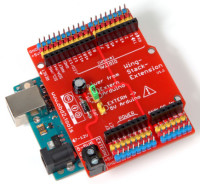
The solution is the new wing stack extension board: It is plugged onto the Arduino Uno and offers the same four socket strips as the Arduino, which are looped upwards from this so that further HATs can be attached. In addition, all pins are led to the outside into further jumper cables can be plugged - even if a HAT is attached. Next to each I / O pin there are also pin headers for GND and VCC (the arrangement corresponds to that for servomotors). The colored pin headers help avoid wiring errors.
The board is a little shorter than the Arduino Uno, so that there is no contact with the USB socket etc. There is a screw terminal on the board to which an external voltage source can be connected. A jumper can be used to choose how the board is supplied with voltage: via the external power supply or via the Arduino. In addition, the Arduino can be supplied via the external supply. A diode protects against polarity reversal and the capacitor reduces high-frequency interference and voltage drops.
The diode limits the maximum possible current from the external voltage source. The technical data can be looked up in the data sheet. A 1N4004 can withstand a maximum of 1 A (I F ) and has a forward voltage V F of 1.1 V. With an SB 330 Schottky diode, I F is 3 A and V F is only 0.49 V. The forward voltage must be added to the external voltage so that the desired voltage is applied to the pins. For the usual 5 V, the external voltage source for a 1N4004 must therefore supply 6.1 V.
With jumper J1 (both pins are short-circuited by a jumper) in the position 1-2 is the external voltage to the red pin strips to: can be selected, where the red 5V headers receive their voltage. If the jumper is in position 2-3, the voltage from the Arduino (USB or hollow socket) is fed to the red pin headers. Note that then only a low current carrying capacity is possible, as is otherwise also possible with the Arduino.
If jumper J2 is also short-circuited (J1 is then irrelevant), the external voltage is also fed to the Arduino via pin 5V. Make sure that the voltage behind the diode is never more than 5 V, otherwise the Arduino will be destroyed. This can be measured at the cathode of the diode (the side with the surrounding ring marking). In addition, the Arduino must not be supplied via another voltage source (USB or hollow socket)!
A wing stack extension component with all connections is available for download for the Fritzing software , which you can add to the program.
One problem is that the boards are often short-circuited via the USB socket of the Arduino because the distance between the Arduino and the board is too small and the solder pads on the board touch the USB socket. In addition, you can then no longer access the pins of the Arduino and no further hardware can be connected.
Another problem is that there are too few slots for ground (GND) and 5 V on the Arduino.
So-called sensor shields provide a solution here and, in addition many I / O pins, also offer two pins for the supply. This also makes it easy to connect servos with the usual three-pin connector. The arrangement of the pins is rather random and not like the Arduino is used to. Depending on the expansion board, another board (HAT: hardware attached on top) can be attached - but then the pins on the sensor shield are no longer easily accessible, so that the board actually loses its meaning.
The solution is the new wing stack extension board: It is plugged onto the Arduino Uno and offers the same four socket strips as the Arduino, which are looped upwards from this so that further HATs can be attached. In addition, all pins are led to the outside into further jumper cables can be plugged - even if a HAT is attached. Next to each I / O pin there are also pin headers for GND and VCC (the arrangement corresponds to that for servomotors). The colored pin headers help avoid wiring errors.
The board is a little shorter than the Arduino Uno, so that there is no contact with the USB socket etc. There is a screw terminal on the board to which an external voltage source can be connected. A jumper can be used to choose how the board is supplied with voltage: via the external power supply or via the Arduino. In addition, the Arduino can be supplied via the external supply. A diode protects against polarity reversal and the capacitor reduces high-frequency interference and voltage drops.
The diode limits the maximum possible current from the external voltage source. The technical data can be looked up in the data sheet. A 1N4004 can withstand a maximum of 1 A (I F ) and has a forward voltage V F of 1.1 V. With an SB 330 Schottky diode, I F is 3 A and V F is only 0.49 V. The forward voltage must be added to the external voltage so that the desired voltage is applied to the pins. For the usual 5 V, the external voltage source for a 1N4004 must therefore supply 6.1 V.
With jumper J1 (both pins are short-circuited by a jumper) in the position 1-2 is the external voltage to the red pin strips to: can be selected, where the red 5V headers receive their voltage. If the jumper is in position 2-3, the voltage from the Arduino (USB or hollow socket) is fed to the red pin headers. Note that then only a low current carrying capacity is possible, as is otherwise also possible with the Arduino.
If jumper J2 is also short-circuited (J1 is then irrelevant), the external voltage is also fed to the Arduino via pin 5V. Make sure that the voltage behind the diode is never more than 5 V, otherwise the Arduino will be destroyed. This can be measured at the cathode of the diode (the side with the surrounding ring marking). In addition, the Arduino must not be supplied via another voltage source (USB or hollow socket)!
A wing stack extension component with all connections is available for download for the Fritzing software , which you can add to the program.
Build This Project
Bring this design to life with the Elektor PCB Service, powered by Eurocircuits. Upload the project files and order professionally manufactured PCBs or assembled boards through a proven European production platform.
Supporting KiCad, Eagle, Gerber, and ODB++ formats, the service is suitable for everything from prototypes and validation builds to series production and volume manufacturing.
Made in Europe. Fast. Reliable. Professional.
Discussion (0 comments)