
Buffer Boards for Raspberry Pi 2/3
All 26 GPIOs are buffered with bi-directional voltage translators to protect the RPi when experimenting with new circuits. Normal and T-board version. Order now on GroupGets!
Update December 20, 2018 - Order now on GroupGets!
We have not yet produced this board. The rectangular version (PCB 150719-1) is now on GroupGets. Sign up for one or more here. If 100 boards or more are requested/ordered/funded we will launch a production run.End of update
The boards are based on project ‘Raspi buffer board’ (article nr. 180430)
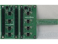
We made two versions. The first one is a compact PCB of 35.6 x 64.8 mm (PCB 150719-1) and second one is a T-board version for use with a breadboard (PCB 150719-2, Two for T). All 26 GPIOs are buffered but also SD and SC. These two are used to address an EEPROM for identification of Pi HATS (Hardware Attached on Top).
The pull-down resistor of a GPIO as input (if set) is useless if the buffer board is connected. The buffers used are of type TXS0108E and are bidirectional. Each port has a pull-up resistor. The pull-down resistor of a GPIO of the RPi is typically in the order of 40 to 60 kΩ. This is too high. Each A-port I/O of the TXS0108E has a pull-up resistor to VCCA and each B-port I/O has a pull-up resistor to VCCB. These pull-ups have a value of 40 kΩ when the output is driving low and a value of 4 kΩ when the output is driving high. So the outputs of the buffers are in fact open drain. If for instance a led is connected from the output of the buffer to ground a voltage divider is created when an extra series resistor is used. A resistive load on the output will cause the logic high level to drop. Something to keep in mind!
Two python programs are attached. One is to test all GPIOs as output (Check_all_GPIOs_as_output.py) and the other is to test all GPIOs as input (Check_all_GPIOs_as_input.py). When testing the GPIOs as output only 8 low current leds are needed with the attached python program. Outputs are tested in group of eight. As a series resistor for the leds 1.8 kΩ can be used, but the value is not that critical. It will prevent damaging the led if connected to the plus directly. Because of the open drain output the voltage across a led (red) plus resistor is about 2.6 V when the 5 V is selected as a power supply for the outputs (JP3).
Both PCBs have two resettable fuses (F1, F2) to protect the +5 V and +3.3 V power supply of the RPi. Additionally for I2C extra pull-up resistors R1 and R2 can be enable by jumpers JP1 and JP2. The B-port I/O’s of the ICs (these are the buffered ports of the PCB’s) can be set to +3.3 V or +5 V logic by jumper JP3.
Connecting the RPi side of the PCBs can be done by a short 40way ribbon cable with two 2x20 receptacle connectors if K1 is an ordinary 2x20 pin header. It is also possible to use a 2x20 female extra tall GPIO Stacking Header for K1 as most HATs do and place the PCB directly on top of the RPi. In case of the T-Board this may not be such a good idea. The breadboard must then be placed on exactly the right height, but you would also still be able to place a HAT on the RPi.
The output of 150719-1 can also be connected to the external circuit by way of a short 40way ribbon cable with two 2x20 receptacle connectors attached or single sockets with short wires soldered to them.
The board-to-board connector from Harwin with 32 contacts we used in our T-board prototype to connect the PCB to a breadboard has to be split in two 16 connectors (K2,K3). Each contact has a thicker and thinner pin. The thicker part of the contacts should be soldered to the PCB.
Bill of materials PCB 150719-1 v1.0
Resistor
R1,R2 = 10 kΩ, 100 mW, 1 %, SMD 0603
Capacitor
C1-C8 = 100 nF, 50 V, 10 %, X7R, SMD 0603
Semiconductor
IC1-IC4 = TXS0108EPWR, SMD TSSOP-20
Other
K1 = Pin header, 2x20, vertical, pitch 2.54 mm or 40-pin GPIO Stacking Header - 2x20 Female - Extra Tall
K2 = Pin header, 2x20, vertical, pitch 2.54 mm
JP1,JP2 = 2-way pinheader, vertical, pitch 2.54 mm
JP3 = 3-way pinheader, vertical, pitch 2.54 mm
JP1,JP2,JP3 = Shunt jumper, 2.54 mm spacing
F1,F2 = PPTC Resettable Fuse, smd, polyfuse, 1210L050YR Littelfuse
Misc.
PCB 150719-1 v1.0
Bill of materials PCB 150719-2 v1.0 (T-board version)
Resistor
R1,R2 = 10 kΩ, 100 mW, 1 %, SMD 0603
Capacitor
C1-C8 = 100 nF, 50 V, 10 %, X7R, SMD 0603
Semiconductor
IC1-IC4 = TXS0108EPWR, SMD TSSOP-20
Other
K1 = Pin header, 2x20, vertical, pitch 2.54 mm
K2,K3 = 32 Single row male mating pins for IC socket (2x16), D01-9923246 Harwin
JP1,JP2 = 2-way pinheader, vertical, pitch 2.54 mm
JP3 = 3-way pinheader, vertical, pitch 2.54 mm
JP1,JP2,JP3 = Shunt jumper, 2.54 mm spacing
F1,F2 = PPTC Resettable Fuse, smd, polyfuse, 1210L050YR Littelfuse
Misc.
PCB 150719-2 v1.0
Want to build a project?
Bring your design to life with the Elektor PCB Service, powered by Eurocircuits. Upload the project files and order professionally manufactured PCBs or assembled boards through a proven European production platform.
Supporting KiCad, Eagle, Gerber, and ODB++ formats, the service is suitable for everything from prototypes and validation builds to series production and volume manufacturing.
Made in Europe. Fast. Reliable. Professional.
Discussion (1 comment)