
Decimal Clock
Update:New software V2.2 is up and running.Additions are:Hardware:Maxim Integrated DS3231 RTC for time keeping.LCD controlled by another MCP23017.Software:
Update:
New software V2.2 is up and running.
Additions are:
Hardware:
Maxim Integrated DS3231 RTC for time keeping.
LCD controlled by another MCP23017.
Software:
LCD displays regular time in either 12h or 24h format, Date in MM/DD/YYYY or DD/MM/YYYY format, Temperature in Fahrenheit or Celsius.
LCD menu for setting time and LCD display formats.
A 48 tick countdown timer for lunch break.
To Do's:
Setting for LED display to show either:
-full decimal time (Astronomical clock [thank Jean-Pierre for the hint])
-24h clock with decimal "minutes" (as it is right now)
-regular 24h clock
-regular 12h clock.
Holding current settings in non volatile memory of RTC.
Update:
I just got my RTC module in.
So now I'm updating the software.
I hope to have some new code soon. Between work and home life there is only so much time to tinker...
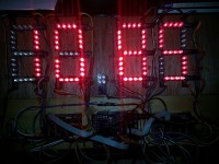
Oh no, not another clock.... Anyways, The decimal clock was developed for my work break room. At my work place we use time clocks that show decimal time. That is a 24h clock that uses a decimal (0-99) "minute" instead of the 1/60 hour (0-59) minute per hour. For example 13.50 on the time clock is 1:30pm on a "regular" clock. It is a bit annoying if you clock out for lunch in decimal time and have only regular analog clocks in the break room. So if I clock out for lunch at 19.08 for my half hour lunch I will have to clock back in at 19.58. Now 8 ticks decimal (36 seconds) are pretty close to 5 minutes (4.8 minutes). So I would want to run back to the time clock to punch back in at around 7:54pm to make it back in time to clock in from lunch on time. Not that it is rocket science to convert 60 minute hours to 100 tick (with one tick being 36 seconds) hours, but it is annoying. So I decided to build a decimal clock around an Arduino just using my development boards and some software. I did add an LED strip board to create a "giant" LED to make the clock very visible. The finished product still needs a housing and a smoked acrylic window for the giant LED display.
The size of the display as built is about 11" W x 3 1/2" H or 27cm W x 9cm H
Each seven segment digit is about 2" W x 3 1/2" H
The LED I chose is CREE C503B-RCN-CW0Z0AA1
Datasheet for the LED here:
This LED is super bright. It was chosen for it's extreme brightness so it could be used in brightly lit areas or even outside in bright sunlight. The LED is designed for outside use so it's perfect for large outside LED signs or displays.
The LED strips are designed to be driven by up to 12V at maximum brightness at 20mA. For inside use 9V is a better choice to keep brightness "bearable".
The whole clock can be powered from a small 9V wall wart that can supply 1A. But maximum current draw with all LED's lit at 9V should not exceed 600mA.
The clock is built using four different kinds of small PCB's
2x Port Expander MCP23017 driving High Efficiency LED strips with four LEDs each using two ULN2803. Each Port Expander board drives two seven segment digits and a dot.
1x Arduino Shield for easy access to I2C and digital I/O
1x keypad with two buttons for adjusting the time.
1x 4 5mm LED dot
28x 4 5mm LED strip
All PCBs were done in DesignSpark 6.0.
Since each LED segment strip is driven by an MCP23017 output there is no need for multiplexing or a switch matrix to drive the display. This keeps the software simple and load on the microcontroller minimal. The display is only updated once a second. The Arduino sketch is pretty much self explanatory. But I will add better commenting in the near future.
All in all this could be a nice weekend project for the beginner playing with Arduino. I will add a complete BOM with Mouser part numbers and approximate prices when time permits. If there is interest the PCB's can be ordered through OSHpark PCB service.
Just add a comment and I will answer any questions.
Planned additions / changes:
RTC module for more precise time keeping. At this point time is kept merely using millis timer on Arduino.
Creating some kind of a mounting board with connectors to plug the LED strips in to form the big LED display. This would make the wiring much more sightly and faster.
The driver board could be made much smaller going all SMT. I just happen to have a large amount of ULN2803 in the DIP package.
The developed boards are part of a rapid prototyping system with standardised connectors I am currently working on.
If there is interest I will design a PCB that will incorporate everything (except the LED display) on one board.
Addition of analog dial driven by small stepper motors.
P.S. With just a few changes in the software this can be a regular clock... Just happened that I needed a decimal clock...
Want to build a project?
Bring your design to life with the Elektor PCB Service, powered by Eurocircuits. Upload the project files and order professionally manufactured PCBs or assembled boards through a proven European production platform.
Supporting KiCad, Eagle, Gerber, and ODB++ formats, the service is suitable for everything from prototypes and validation builds to series production and volume manufacturing.
Made in Europe. Fast. Reliable. Professional.
Discussion (1 comment)