


ESP-01 / ESP-03 programmer
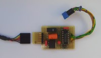
This project allows to program an ESP-01 or ESP-03 module, in-circuit or stand-alone.
Introduction:
This circuit allows to program an ESP-01 or ESP-03 FLASH, with the following advantages:
- Places the ESP-01/03 in programming mode by only pressing a single button.
- Allows to use a USB-Series cable type FTDI 5V, making the necessary voltage level conversion.
- Can be used to program an isolated or in-circuit ESP (mounted on the final board).
Operation:
The circuit has been tested with an Arduino IDE 1.6.11 environment, choosing "Generic ESP8266 Module" on “Tools – Board” menu.
The 3.3V power can be supplied from the programmer or by the circuit itself. Place switch S2 or S3 in the proper position before starting.
A short press on button S1 forces a reset to the circuit. A long press forces de circuit to enter programming mode, ready to receive a new sketch.
R4 is necessary since it seems that GPIO0 behaves as an output in the programmer and cannot be connected directly to the output of IC2C gate.
Figure 1 shows the electronics circuit diagram.
In Figures 2 and 3 you will find the minimum circuit to program/run an ESP-03 or ESP-01 respectively.
Remarks:
This circuit allows to program an ESP-01 or ESP-03 FLASH, with the following advantages:
- Places the ESP-01/03 in programming mode by only pressing a single button.
- Allows to use a USB-Series cable type FTDI 5V, making the necessary voltage level conversion.
- Can be used to program an isolated or in-circuit ESP (mounted on the final board).
Operation:
The circuit has been tested with an Arduino IDE 1.6.11 environment, choosing "Generic ESP8266 Module" on “Tools – Board” menu.
The 3.3V power can be supplied from the programmer or by the circuit itself. Place switch S2 or S3 in the proper position before starting.
A short press on button S1 forces a reset to the circuit. A long press forces de circuit to enter programming mode, ready to receive a new sketch.
R4 is necessary since it seems that GPIO0 behaves as an output in the programmer and cannot be connected directly to the output of IC2C gate.
Figure 1 shows the electronics circuit diagram.
In Figures 2 and 3 you will find the minimum circuit to program/run an ESP-03 or ESP-01 respectively.
Remarks:
- Both 4K7 resistors are essential so that the circuit can work disconnected from the programming cable.
- 470uF capacitor in parallel with ESP power supply is mandatory to maintain VCC stable while programming.
Want to build a project?
Bring your design to life with the Elektor PCB Service, powered by Eurocircuits. Upload the project files and order professionally manufactured PCBs or assembled boards through a proven European production platform.
Supporting KiCad, Eagle, Gerber, and ODB++ formats, the service is suitable for everything from prototypes and validation builds to series production and volume manufacturing.
Made in Europe. Fast. Reliable. Professional.
Discussion (0 comments)