Get started with LoRa, LoRaWAN and The Things Network using ready-made modules.
LoRaWAN that is becoming more and more widespread is "The Things Network", a free, community-based network with growing coverage. This also means that participating in this network requires only a registration and suitable hardware. There is no monthly fee, or billing per message, but you have to follow the Fair Use Policy in the network. This policy is intended to enable all participants to transport their data and to prevent gateway overload. However, the solution presented here is only suitable for experimentation and does not fully conform to the LoRaWAN specifications.
The cost of the sensor is about 23 Euro plus possibly a plug-in board and jumper wire. The ingredient list for a LoRa sensor is quite simple, we need:
For a cheap start we take here something Arduino compatible with a little more power for a small price. A Blue Pill board with an STM32 on it. This is already available for a few Euros including debugger and offers 64kB Flash and 16kB RAM as well as USB. And with the latter it comes unfortunately again and again to problems, since the wiring on the boards is very cost-optimized the board is not recognized cleanly at a part of the computer, therefore the USB port should be regarded here rather as simple power supply. To program the chip it has a fixed bootloader and can be supplied with new software via serial interface or theoretically via USB, whereby the serial interface for programming works most reliably with the board.
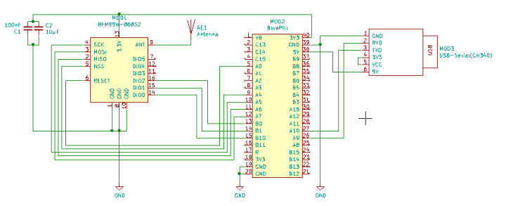
To connect the components together we use the circuit diagram below. Figure 1 shows the connections between the LoRa module and the BluePill board and a USB-to-serial converter.
Since the LoRa module with a grid dimension of 2.00mm is not pin board friendly, there is now a small breakout board (Fig. 2) with which the module can not only be plugged comfortably onto a pin board, but also the two capacitors C1 and C2 can be mounted directly on the board.
What's missing is an antenna. A piece of copper wire with a diameter of 1mm is perfectly sufficient. The required length is calculated as λ/4 antenna for the 868Mhz, the range in which the LoRa module operates, as follows
λ/4=(C0/868MHz)/4= (299792458 m/s)/(8680000 1/s*4)=0,08635m=8,635cm
This length applies if wave would propagate in vacuum, but in copper the speed of the wave is lower and a shortening factor must be considered. With the value 0.95 you get an approximation with a length of 8.2cm at the end for the copper wire.
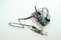
As you can see in picture 3, not much is needed for the construction and the hardware of our sensor is ready. For the first tests no further external sensors will be used, but it will be shown how such a sensor, or node, is set up and put into operation. First of all it needs some software in form of the ArduinoIDE, the MCCI LoRaWAN LMIC library and the Arduino-Core-STm32 board support package.
The LMIC library can be installed as usual from the libraries.
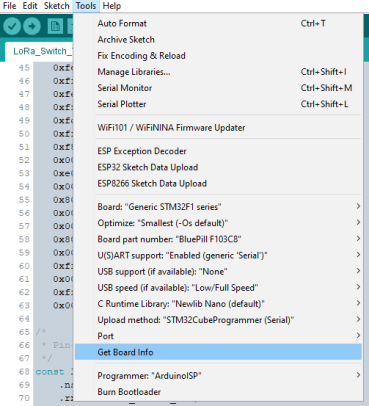
For the BluePill Board we need to add a URL to the Additional Boards Manager URLs. Under Data -> Settings we have to add "https://github.com/stm32duino/BoardManagerFiles/raw/master/STM32/package_stm_index.json". Then we can search for "STM32" in the Boards Manager and install "STM32 Cores". So we have all the libraries we need with each other. The last step before we get to the source code are the settings we have to make for the board, which can be taken from picture 5.
Now you can almost start with the code, you still have to set in the folder of the LMIC library in which part of the world we are and if it is a SX1276 LoRa module (the RFM95 is such a module). In the library order in which the LMIC library is located, the following must be set in the file "\project_config\lmic_project_config.h" for Europe
Before going any further, the difference between OTAA (over the air activation) and APB (activation by personalizaion) must be mentioned. With OTAA, the LoRa Node actively joins the network and receives a device address from the network and exchanges keys with the network. This is the preferred way to participate in the network at "The Things Network". In APB mode, the device address and keys for the device are permanently stored in the code. This makes it easier to put the node into operation, but leads to a weaker security of the node. For more details about this topic it is worthwhile to have a look at the documentation provided by "The Things Network" [ https://www.thethingsnetwork.org/docs/lorawan/ ].
The ttn-abp example from the LMIC library is used as output point. The code sends a "Hello, world!" every 60 seconds and requires some hardware adjustments. From line 86 on the pin mapping is replaced by the following lines:
It turned out that for the LMIC the clock error, i.e. the deviation of the MCU's timebase, must be reset within the source code. Without the settings, an error of 0% is assumed, which can lead to problems when receiving messages from the gateway if the MCU's timing deviates a little more.
In the setup() function the following is inserted as the last line with Insert:
LMIC_setClockError(MAX_CLOCK_ERROR * 1 / 100);
This means that an error of 1% is calculated internally for the time base
In the Arduino sketch, the network data for the node must be set up in addition to the pin configuration. In order to get these, it is necessary to create a new node at The Things Network and to transfer the access data there.
How to get the Software into the STM32
To get the Code into the hardware it is sufficient to use a simple USB serial converter ( Link to Elektorshop ) and four jumper wires, female-female.
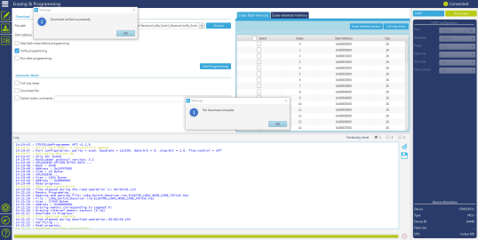
If the software is provided as hex file it can be programmed with STM32CubeProgrammer. To do this, the chip must be in bootloader mode, which is achieved by pressing Reset while Boot is shorted.
As soon as the chip is in bootloader mode, the appropriate serial interface can be selected via Connect and Connect can be pressed if no error message appears.
After successful programming, the chip can be taken out of the bootloader mode by reset and starts to execute the firmware.
If you do not only want to program the firmware into the chip, you can also use the ArduinoIDE to recompile the firmware for the chip and make your own adjustments. If you install the current version 1.8.0 via the Arduino-Boardmanager, be warned that there are some bugs that can cause the firmware to crash. With the latest version from the github repositories of the STM32duino project these bugs are fixed.
The settings for the board for the ArduinoIDE can be seen in the following screenshot
Make sure you are using the corresponding serial port for upload.
Creating a TTN Device
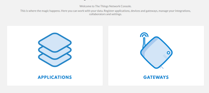
For "The Things Network" a user account must be created ( https://account.thethingsnetwork.org/register ), so that the nodes can be created and managed. So that the nodes are not simply listed in a huge list, they are arranged below the applications, so that nodes can be grouped together for each purpose. After login, "Applications" and "Gateways" can now be managed via the "Console", as shown in Figure 6. Figure 6 - TTN console
If there is no gateway nearby that can be used, you can run your own operation and make it available to other users nearby. Setting up your own gateway comes a little later.
Figure 7
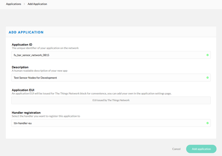
In order to generate a suitable file for the node, an application must first be created by clicking on the APPLICATIONS icon (Figure 6), followed by the item "add application", as shown in Figure 7. Fugure 8
After filling in the necessary data, as shown in figure 8 as an example, the creation can be finished with "Add application". Nodes can now be added in the created application by clicking on the "register devices" item. This point can be seen in figure 9.
Figure 9 Figure 10
In the dialog that now opens (Figure 10), the name of the node must be entered and the Device EUI must be set to "this field will be generated" by clicking on the symbol with the crossed arrows.
Figure 11
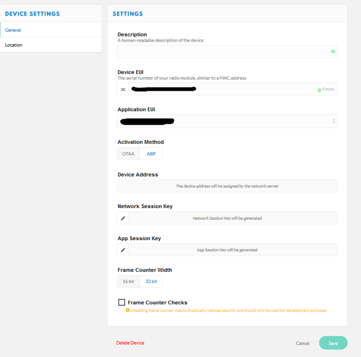
On top of confirming the data with register, a new node is created, whose data we can now almost use. Under Settings, as shown in Figure 11, the "Activation Method" is changed from OTAA to ABP. For the first experiments the checkbox "Frame Counter Checks" is deactivated. For a productive operation this is risky and should be reversed urgently after the first successful steps.
By clicking on Overview, all the data required for the node is available at a glance, the Device EUI, the Application EUI and the App Key ( Figure 12 ). A stoplert-block is here in the data format whether the fields LSB or MSB must be transferred. For the Sketch, Device EUI and Application EUI are required as LSB and the App Key as MSB array.
Figure 12
By clicking on "< >", the functions for switching between MSB and LSB become visible (Figure 13).
Figure 13
This data is now entered in the Arduino sketch in the defines for NWKSKEY, APPSKEY and DEVADDR. If there is a LoRa-Gateway nearby the sketch can be compiled and uploaded without any further changes.
// LoRaWAN NwkSKey, network session key
static const PROGMEM u1_t NWKSKEY[16] = { 'Network Session Key'};
// LoRaWAN AppSKey, application session key
static const u1_t PROGMEM APPSKEY[16] = { 'App Session Key` };
// LoRaWAN end-device address (DevAddr)
// Lake http://thethingsnetwork.org/wiki/AddressSpace
// The library converts the address to network byte order as needed.
static const u4_t DEVADDR = 0x[DEVICE_EUI]; // <-- Change this address for every node!
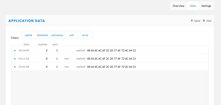
If all goes well we can see that the node has sent data the last time we are in the TTN console (Figure 14). A click on Data then also shows us the user data of the node. Figure 14
No Gateway in range, no problem. Build your own with just a few parts
If no gateway is within range, a separate installation can be made. There are different possibilities from complete commercial solutions to a non LoRaWAN compliant Single Chanel Gateway, consisting of a Raspberry Pi and a LoRaWAN-HAT. A completely compatible gateway is the LPS8 Indor LoRaWAN Gateway from Dragino (about 130Euro), which can receive on all frequency bands used by LoRaWAN in the 868MHz band simultaneously. A cheaper ( 80 euro ) but also more limited in reception is the Dragino LG02, in which two LoRa modules are built in. The gateway comes ready-made in a small white housing and is based on an OpenWRT with a few adjustments for operation as a LoRa gateway. If you already have a Raspberry Pi at home you can equip it with a LoRa module and use it as a gateway. Under (https://github.com/hallard/single_chan_pkt_fwd) a gateway is provided that directly supports the Dragino LoRa HAT ( https://www.elektor.de/dragino-lora-gps-hat-for-raspberry-pi-868-mhz), who wants to be a little cheaper on the road, can directly connect the RFM95 module to the PI with a few jumper wires. With the Breakout-PCB this is very easy to do, with the schematic for the connection you can orientate yourself at ( https://github.com/hallard/single_chan_pkt_fwd ) and follow the pin definition for the Dragion LoRa HAT. For installation, follow the instructions at ( https://github.com/hallard/single_chan_pkt_fwd ). With this gateway a node can only be operated in ABP mode and a transport of messages from the LoRaWAN to the node is not possible. The channel and the spread factor must also be permanently set in the node. If you want to get started faster and with fewer stumbling blocks but a little more expensive, you can use the Dragino LG02, where OTAA mode is also possible and sending data to nodes from the LoRaWAN.
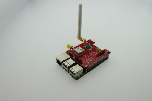
For convenience and bad experiences with RFM95 and Jumper Wires a Dragion LoRa Hat ( as shown in picture 15 ) is used for the test run and a new Raspbian Image is used for the Raspberry Pi. The hardware used is a Pi 3B+ left over from the WirelessCar Voltmeter project and the Dragion LoRA Hat from the Elektorshop. Figure 15
Once everything is assembled and the SD card, monitor, mouse, keyboard and Ethernet cable for Internet access are connected, the first boot can take place. After the basic configuration known from other articles the system now shows the desktop and it is necessary to open a terminal to adjust some hardware settings.
With "sudo raspi-config" you can access the configuration for the Pi. The item "Interface Options" must be selected. In the following the point "P4 SPI" is selected and the question if the interface should be activated is answered with "Yes". After a reboot the SPI interface is active and the configuration can be continued.
A terminal must be opened again to download some packages and the source code for the package forwarder. The source code is made available via GitHub, so we get the latest version with a "git clone https://github.com/hallard/single_chan_pkt_fwd.git" on the console. But before we can build the program, a few more libraries must be installed. In the terminal we install with "sudo apt-get install wiringpi" the WiringPi library we need for compiling. With a "cd single_chan_pkt_fwd" the terminal now changes to the directory with the downloaded source code. Now with "make" first the source text is translated into a program and then installed with "make install".
With this the gateway is basically set up, but the pin configuration has to be adjusted in the "global_conf.json" for the LoRa-hat. The following configuration can be used for the dragiono hat:
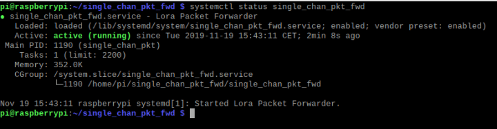
With this the gateway then listens on 868.1MHz with SF7. In order to send data to the TTN some small settings have to be made. First the dgateway must be restarted for the changes that have just been made. To do this, enter "systemctl stop single_chan_pkt_fwd" in a terminal and then "systemctl start single_chan_pkt_fwd". Now the gateway is set up as a service or can be run directly under the root user. To query the status of the service this can be done with "systemctl status single_chan_pkt_fwd" and should look like this:
Picture 16
[Screenshort terminal service okay]
The Gateway is now ready for operation, but it must still be set up in the TTN so that the packets can also be assigned and the Gateway can be administered.
To do this, click on the icon "GATEWAYS" in the console of The Things Network and then "register gateway
Figure 17 Figured 18
The checkbox "I'am using the legacy Semtech packet forwarder" must be checked. For the Gateway EUI we have to take the MAC address of the Raspberry Pi and fill in the middle with "FF FF". We get this on the Raspberry Pi in the terminal by the command "cat /sys/class/net/eth0/address" for our network card. Now if the output is "b8:27:eb:12:34:56" we insert "B8 27 EB FF FF 12 34 56" in the Gateway EUI field in the console of The Things Network.
Figure 19
By clicking on the Gateway tab, the gateway is now ready for use.
In order for the LoRa node to work with the gateway, it must be set to a defined frequency and spreading factor in the source code. Additionally it is necessary to limit the node to the frequency defined in the gateway. The extract from the following source code shows the adjustments for the LoRa node. A complete example can be downloaded from the Labs page.
…
// Disable link check validation
LMIC_setLinkCheckMode(0);
// TTN uses SF9 for its RX2 window.
LMIC.dn2Dr = DR_SF9;
// Set data rate and transmit power for uplink (note: txpow seems to be ignored by the library)
LMIC_setDrTxpow(DR_SF7,14);
//If we have a single channel one module gateway we need to add these lines
// Define the single channel and data rate (SF) to use
int channel = 0;
int dr = DR_SF7;
// Disable all channels, except for the one defined above.
// FOR TESTING ONLY!
for(int i=0; i<9; i++) { // For EU; for US use i<71
if(i != channel) {
LMIC_disableChannel(i);
}
}
// Set data rate (SF) and transmit power for uplink
LMIC_setDrTxpow(dr, 14);
// Start job
do_send(&sendjob);
…
Thus the node is set to 868.1MHz and SF7. We also use these values in our gateway.
If the Gateway and the node are now supplied with software, nothing stands in the way of a test. After a short time new messages from our accounts should arrive in the TTN console.
For the first steps with LoRaWAN very simple means are sufficient, a node for about 25 Euro and a gateway based on a Raspberry Pi and RFFM95 module. However, this solution has severe limitations and is not suitable for productive operation. If you find out after experimenting that you want to do more with LoRaWAN you should exchange the gateway for a completely LoRaWAN capable one. These are now available for less than 130 Euro (link to the Elekotrshop) and allow the full potential, including messages from the gateway to the node, to be used. One point we have not yet considered is to retrieve the data from "The Tings Network" and process it further. This will be shown later with the LoRa GPS Tracker.
Build This Project
Bring this design to life with the Elektor PCB Service, powered by Eurocircuits. Upload the project files and order professionally manufactured PCBs or assembled boards through a proven European production platform.
Supporting KiCad, Eagle, Gerber, and ODB++ formats, the service is suitable for everything from prototypes and validation builds to series production and volume manufacturing.
Elektor Magazine has been one of the leading sources of information on electronics for engineers, designers, start-ups and companies for 65 years. Our magazine is powered by an active community of electronics engineers – from students to professionals – who are passionate about designing and sharing innovative ideas.
For them, we publish hundreds of items a year, in formats such as articles, videos, webinars, and other learning formats. Our mission is to share knowledge in every possible way and inspire readers with the latest developments within the electrical engineering sector.
Thank you for your vote!
Leave further comments in the fields below.
Thank you for your vote!
If you wish to leave a comment with your rating, please first use the login below. If not, just close this window.


Discussion (0 comments)