
LPC810 as DCF77 decoder (and I2C slave)
After making the LPC810 reading IR remote controls (www.elektor-labs.com/project/lpc810-as-ir-decoder.14053.html) I thought of another idea to use the little 8-pin device for. And that became the DCF77 decoder presented here. Like decoding IR remote controls, decoding the Frankfurt time signal takes only one GPIO input - to connect to a DCF receiver board (Conrad# 641138).
After making the LPC810 reading IR remote controls (www.elektor-labs.com/project/lpc810-as-ir-decoder.14053.html) I thought of another idea to use the little 8-pin device for. And that became the DCF77 decoder presented here. Like decoding IR remote controls, decoding the Frankfurt time signal takes only one GPIO input - to connect to a DCF receiver board (Conrad# 641138).
A program to detect the timepulses received and interpret them to time and date format is done before by many others. The 'extra' is in the communication with an other uC or multitasking system like a Raspberry Pi. After gaining the date and time information I did not want to force a master system to pay attention to the LPC810. That means that I did not want to use a UART interface. So (poor me) I decided to configure the LPC810 as a I2C slave. Why poor me? Because all the examples I found are for the LPC810 to act as I2C-master .. or are not compiling or buildable. I still think it is a show of conceit to think that a 8-pin uC can be the focus of a large automated system (and act as 'master'). But I succeeded and want to share it with you.
Hardware
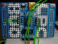
Look for the downloadable Schematic.jpg on how to connect the DCF77 receiver board. It is not difficult; solder some female pinheader on the LPC800 miniboard and put wires in them to go to 3V3, GND and the inverted output of the DCF77 receiver board screw clamps. The inverted output is used because the signal perfectly connects to PIO0_2. And that signal is also connected to the small blue led on the miniboard. Every time the DCF77 receiver board pulls the input down (when a pulse occurs) the blue led lights up. A nice way to check if the pulses come in to the PIO0_2 pin.
To test the I2C-slave part I used a ST NUCLEO F103RB, programmed with mbed, as a I2C test master. How to connect those two you see in the Testschematic.jpg.
Now pay some extra attention to the 6-pin connector on the LPC800 miniboard. Because the normally present RxD (pin 5 – yellow) and TxD (pin 4 – orange) pins will become the SCL and SDA pins. Also look at het photos. So after you flashed the program, disconnect the USB cable, put the connector of the LPC800 miniboard in a breadboard and connect SDA (pin 4), SCL (pin 5), 3V3 (pin 3) and GND (pin 1). The Reset and the ISP buttons on the LPC800 miniboard stay available and working.
Software
If you like to have a look at the program, download the NECV20HisDCF77-i2c.zip and store it somewhere on your harddisk. Remember where you stored it. Then start LPCXpresso, choose a new workspace and then select Import project(s) from the the Quickstart Panel menu on the left lower corner of the screen. Browse to the map where you stored NECV20HisDCF77-i2c.zip. After importing you can pull the project open. Everything necessary to 'build' it, is in the project. Look in the list of src (sources) for the sourcefiles. The program is based on the LPC810_Codebase of K.Townsend (microbuider.eu). With some additions of course. It works with special registers for status and commands instead of ROM based drivers. The flashable (with Flashmatic) .hex file is in the Release map in the workspace.
Some software details
Although most of the software (with comments) is selfexplaining (I hope: the DCF77 decoding in main.c), lets go further in some details. Software setting the hardware: After you setup the hardware, the LPC810 needs to be told how to use its pins. And this has to be done by software (huh?). First you have to marshall PIO0_2 to the GPIO-unit and PIO0_0 and PIO0_4 to the I2C-unit inside the controller. That is done by the switch matrix. I used the switch matrix tool to do that for me – it generates a file swm.c with function SwitchMatrix_Init(), which I copy and paste in main.c. And (grrrr...) after that I change it by hand, because I cannot instruct the switch matrix tool to use PIO0_5 as ISP pin. You see a comment about this above the SwitchMatrix_Init () function in main.c of what to alter. Ready to go now? Noop! Because somebody at NXP thought it a good idea to have all pins have there pull-up resistor connected by default. And for the SDA and SCL pins we can not have that. And the switch matrix will not do that for you! So something like IOCON has to be changed, for which in a certain register a clockpulse has to be started, which we, after setting IOCON, can switch off again (or not). But also do not forget to start a clockpulse for the I2C-unit in the controller, which by the way (are you still following this?) is not a clockpulse for the SCL signal. The LPC810 in this case uses a master pulsing the SCL line. Do not bother to study further – use I2c_Init (0, 4). Pffff. That said and done, for the LPC810 to act as a I2C-slave there are a few checks left to do; call I2cAsSlave (0xDC) one time to set the slave address (I thought 0xDC rather appropriate – as long it is a even address) and check now and then if the master has anything to command: I2cSlaveAdressed (), I2cMasterWantsToSend (), and I2cMasterWantsToReceive (). To send the complete date and time and statusbyte on request of a master takes less than a millisecond. If you could follow all this, you can use the LPC810 as a I2C-slave for anything you like in the future – which cannot be much with 2 pins left available. Although, lets admit it. This program is less than 2k, which is pretty good compiling and code generating. And it takes a master system off the tidious task of following and timing a DCF77 signal.
Remaining question: correct reaction to I2C command?
There is one question, you, if you are a bit familiar with the I2C protocol, might help with. The program now has two 16 bytes arrays for sending and receiving data to and from the master. But what if the master sends more bytes than 16 or reads more than 16? Remember the LPC810 is a slave – following what a master demands (is that why everyone only likes to program only i2c-masters?). In the current version the program simply ignores every byte send by the master above the sixtienth. Likewise after giving 16 bytes to the master, and the master wants more, simply null-bytes are send. Is this correct or … should the program at a particular moment start sending NACK's? I don't think this calls for a SOS, but an answer would be welcome – and I will alter the program if necessary and upload it to this project.
Want to build a project?
Bring your design to life with the Elektor PCB Service, powered by Eurocircuits. Upload the project files and order professionally manufactured PCBs or assembled boards through a proven European production platform.
Supporting KiCad, Eagle, Gerber, and ODB++ formats, the service is suitable for everything from prototypes and validation builds to series production and volume manufacturing.
Made in Europe. Fast. Reliable. Professional.
Discussion (2 comments)