
MAX78000FTHR and Arduino Based Vehicle Turn and Warning Indicator
In this project the MAX78000FTHR is used together with an Arduino Uno. The MAX78000FTHR receives voice commands for the required turning and then passes these commands to the Arduino. 4 LEDs are connected to the Arduino to simulate 4 relays. The Arduino runs in timer interrupt mode and flashes the required LEDs every 0.5 seconds. The program also generates warning lights (i.e. all 4 lights flash at the same time). The reason for using another processor (e.g. Arduino) is so that we don't do multitasking.
The video is available at link: https://www.youtube.com/watch?v=U7J9Y0clgkA
MAX78000FTHR and Arduino Based Flashing Lights Vehicle Turn and Warning Indicator: This project is based on the concepts of artificial intelligence where a voice activated flashing light vehicle turn indicator controller is designed using the MAX78000FTHR microcontroller development board and an Arduino Uno. Additionally, all 4 indicator lights are controlled to indicate a Warning situation. The project consists of the MAX78000FTHR, Arduino Uno, level converter module, 4 LEDs to represent the 2 front and 2 rear lights (or relays), and current limiting resistors. By giving voice commands, such as LEFT, the two left indicator lights (front and rear) flash at a rate of every 0.5 seconds. With this project, the driver does not have to operate the indicator arm before making a turning, or operate the warning light button.
At the heart of the MAX78000FTHR is a MAX78000 Cortex-M4 ARM based microcontroller with FPU. Additionally, the board contains 512KB flash memory, 128KB SRAM, 16KB cache, Convolutional Neural Network Accelerator, VGA image sensor, digital microphone, RGB LED, pushbuttons, microSD card adapter, microUSB connector, stereo audio CODEC, SWD debugger, virtual UART port, and many I/O ports.
Why use an Arduino?: In a project with flashing lights, the processor is always busy controlling the lights, unless a multitasking approach is used, or the timer interrupt is used to control the lights. Otherwise, the processor cannot perform other tasks. The MAX78000FTHR program is busy constantly checking the microphone input for audio and it must not be disturbed, otherwise it will not respond to and detect the audio inputs. In this project the MAX78000FTHR detects the voice turn commands and then sends data to the Arduino. The Arduino is programmed to generate timer interrupts and the lights are flashed inside the timer interrupt service routine. This way, the MAX78000FTHR program does not have to flash the lights and is free to check the audio input constantly. The Arduino on the other hand performs just the flashing lights operation.
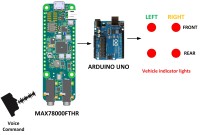
Block Diagram: Figure 1 shows the block diagram of the project. TFT is not used in this project as it is not necessary to display the commands. 4 LEDs are connected to the project to simulate 4 relays (2 for front lights and 2 for rear lights). These lights are controlled with the Arduino Uno after it receives port commands from the MAX78000FTHR development board.
Circuit Diagram: Figure 2 shows the circuit diagram of the project. The output voltages of the MAX78000FTHR are not high enough to drive the inputs of the Arduino. As a result, Ports P2_6 and P2_7 of the MAX78000FTHR are connected to Arduino inputs 8 and 9 respectively through a level converter module. This module converts +3.3V output to +5V necessary for the Arduino inputs. 4 LEDs are connected to ports 2, 3, 4, and 5 of the Arduino. Ports 2 and 4 are connected to the left indicators (lights or relays), and ports 3 and 5 are connected to the right indicators.
The circuit was built on two breadboards, one for the MAX78000FTHR and one for the Arduino Uno, and connections were made using jumper wires. Figure 3 shows the project built on the breadboards.
Power is supplied to the MAX78000FTHR and the Arduino Uno using the USB port of a laptop.
Operation of the project: The following sounds are recognized by the MAX78000FTHR (invalid spoken commands are rejected by the project):
SHEILA: Attention sound. When this sound is spoken, a prompt will be displayed on the TFT telling
the user that he/she can speak a valid command.
LEFT: Flash the two (front and rear) indicator lights (or active relays)
RIGHT: Flash the two (front and rear) indicator lights (or activate relays)
ON: Activate warning lights, where all 4 lights (2 front and 2 rear) flash at the same time
STOP: Turn OFF all lights (or deactivate all relays)
Some example commands are given below in sequence:
SHEILA LEFT Flash the LEFT indicators
SHEILA RIGHT Flash the RIGHT indicators
SHEILA ON Flash all 4 lights (Warning light)
SHEILA STOP Turn OFF all lights
Program listing (MAX78000FTHR): The 20 keywords in the supplied Maxim project kws20_demo has been changed to include the word SHEILA. The CNN training program was ran on a Linux Ubuntu operating system after creating a WMware virtual machine on a Windows 10 machine with an i7 CPU, 100GB disk space, and 12GB free memory, without a special GeoForce GPU. After training the new words, the created cnn.c, cnn.h files and the weights.c and weights.h files were copied to the workspace and program main.c under folder kws20_demo was modified for this project. The full main.c program listing is given in Figure 4 as a PDF file.
Function Detected_Word detects the spoken word and returns an integer number which is used to identify the detected sound. Number 100 is returned if a non-valid sound is detected by the program.
Port pins P2_6 and P2_7 are connected to Arduino inputs 8 and 9 respectively and they are controlled by voice commands as in the following Table:
| Voice command | MAX78000FTHR Ports | Arduino Function
| P2_6 | P2_7
| LEFT | 1 | 0 | Flash LEFT front & rear lights
| RIGHT | 0 | 1 | Flash RIGHT front & rear lights
| ON (Warning) | 1 | 1 | Flash all 4 lights
| STOP | 0 | 0 | All lights OFF
Function ALLOFF clears P2_6 and P2_7, i.e. turns OFF all 4 lights (or deactivated all relays if relays are used). The voice commands are given the following integer numbers to identify them:
10=SHEILA, 11=LEFT, 12=RIGHT, 13=ON, 14=STOP
Program listing (Arduino Uno): Figure 5 shows the Arduino Uno program listing. Inside the setup() routine ports 2,3,4, and 5 are configured as outputs and ports 8 and 9 are configured as inputs. All 4 LEDs are cleared to 0 at the beginning (i.e. all lights are OFF, or all relays are deactivated). The clock frequency is 16 MHZ, and the Timer interrupt 1 of the Arduino is configured to generate interrupts at every 0.5 seconds. Timer 1 prescaler is set to 256 and the timer counter is loaded to generate interrupts at every 0.5 seconds, with the timer overflow interrupt enabled.
The LEDs are controlled inside the timer interrupt service routine as shown below. If for example LEFT_FLASH request is set (i.e. port 8 is logic 1 and port 9 is logic 0), then the LEFT front and rear LEDS are flashed. Similarly, if a warning request is set (i.e. both port 8 and port 9 logic 1) then all 4 LEDs are flashed.
ISR(TIMER1_OVF_vect) {
TCNT1 = tmrcnt;
if(digitalRead(LEFT_FLASH) == 1 && digitalRead(RIGHT_FLASH) == 0)
{ digitalWrite(LEFT_FRONT, digitalRead(LEFT_FRONT) ^ 1);
digitalWrite(LEFT_REAR, digitalRead(LEFT_REAR) ^ 1);
}
else if(digitalRead(RIGHT_FLASH) == 1 && digitalRead(LEFT_FLASH) == 0)
{ digitalWrite(RIGHT_FRONT, digitalRead(RIGHT_FRONT) ^ 1);
digitalWrite(RIGHT_REAR, digitalRead(RIGHT_REAR) ^ 1);
}
else if(digitalRead(LEFT_FLASH) == 1 && digitalRead(RIGHT_FLASH) == 1)
{ digitalWrite(LEFT_FRONT, digitalRead(LEFT_FRONT) ^ 1);
digitalWrite(LEFT_REAR, digitalRead(LEFT_REAR) ^ 1);
digitalWrite(RIGHT_FRONT, digitalRead(RIGHT_FRONT) ^ 1);
digitalWrite(RIGHT_REAR, digitalRead(RIGHT_REAR) ^ 1);
}
else if(digitalRead(LEFT_FLASH) == 0 && digitalRead(RIGHT_FLASH) == 0)
{ digitalWrite(LEFT_FRONT, 0);
digitalWrite(LEFT_REAR, 0);
digitalWrite(RIGHT_FRONT, 0);
digitalWrite(RIGHT_REAR, 0);
}
}
Figures 6.1 to 6.3 show snapshots of the project with the LEDs.
Example run of the project: An example run of the project is shown in the You Tube video link.
Suggestions for future work:
The project can be upgraded such that other electrical units in a vehicle can be controlled by voice commands. For example, opening/closing windows, lights, seat, air conditioning etc etc. A TFT display can very easily be connected to the project if required.
The video is available at link: https://www.youtube.com/watch?v=U7J9Y0clgkA
References
https://www.maximintegrated.com/en/design/software-description.html/swpart=SFW0010820A
https://github.com/MaximIntegratedAI/MaximAI_Documentation/blob/master/MAX78000_Feather/README.md
https://www.maximintegrated.com/en/design/technical-documents/app-notes/7/7359.html
https://www.maximintegrated.com/en/products/microcontrollers/MAX78000.html
https://www.maximintegrated.com/en/design/videos.html
https://www.maximintegrated.com/en/design/technical-documents/app-notes/7/7364.html
Want to build a project?
Bring your design to life with the Elektor PCB Service, powered by Eurocircuits. Upload the project files and order professionally manufactured PCBs or assembled boards through a proven European production platform.
Supporting KiCad, Eagle, Gerber, and ODB++ formats, the service is suitable for everything from prototypes and validation builds to series production and volume manufacturing.
Made in Europe. Fast. Reliable. Professional.
Discussion (0 comments)