
PIC32 Sound Pad
Presentation : This application is for musicians, or DJs. Now there are in almost all songs some effects or sounds that you can't make with your own instrument. With this device, you can with a small JAVA software running on your PC, assign samples to each pad (with the USB stick or your smartphone).
Presentation : This application is for musicians, or DJs. Now there are in almost all songs some effects or sounds that you can't make with your own instrument. With this device, you can with a small JAVA software running on your PC, assign samples to each pad (with the USB stick or your smartphone). A sound is played according to the hit power, and a MIDI instruction is made. The device can also play sounds according to the MIDI instruction received. All these features thanks to a PIC32 chip.
Specifications : The board is used as a USB host, all sounds are stored in a USB stick. Sounds can be assigned directly plugging the USB stick in your computer and using the small JAVA software.
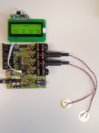
> PADS : 4 pads are used. Each pad is a piezzo sensor which deliver a voltage according to vibrations. A bicolor LED is assigned for each pad, one color normally lighting, flashing when the sound is playing, and the other one lighting when the pad is not assigned. ADC features are used to acquire sensor signal.
> BANKS : 3 buttons allow the user to switch and select banks. A small I2C alphanumeric LCD screen is used to display the banks name.
> USB : The Sound Pad is used as a USB Host. All the samples will be stored on a USB stick plugged to the the Drum Pad. If the USB stick have not been initialized yet by the JAVA software, an error message is printed on the LCD screen. A thing which can be interesting is to run the JAVA software on you smartphone to assign sounds to pads, and after plug it to the Drum Pad.
> MIDI : UART interface is used as a MIDI interface.
> SOUND : When a pad is hit, the sound assigned is played. Several sounds can be played at the same time. The sounds are read in the USB stick and the I2S interface is used to send data to the DAC.
The goal at the end is to be able using a standard file format (SF2/SFZ) :
http://www.sf2midi.com/news/vienna-soundfont-studio.html
http://www.creative.com/soundblaster/soundfont/tutorials/welcome.asp?articleid=54141&page=4
http://www.drealm.info/sfz/
July 11, 2012 : I am working with the Microchip's Microstick II, with a PIC32MX250F128B http://www.microchip.com/stellent/idcplg?IdcService=SS_GET_PAGE&nodeId=1406&dDocName=en556208
July 19, 2012 : Velocity information is now sent through UART connection, according to the stroke on the piezo. I would like to have midi note offset and midi channel setting by user. A threshold can be modified to override some extra pics from the captured signal (default sensitivity : ~26mV). This because, I tested several piezo sensors and some ones had a very bad look after the filter (even with a higher capacitor).
July 30, 2012 : USB is now working well as USB Host. I spent too much time trying to have the USB working with internal oscillator (FRC). It appears, when you set up UFRCEN (use FRC clock source) you can't use USB transmission :
"The USBCLK can be derived from the 8 MHz internal FRC Oscillator, 48 MHz POSC, or the 96 MHz PLL from the POSC. For normal operation, the USB module requires exact 48 MHz clock. When using 96 MHz PLL, the output is internally divided to obtain 48 MHz clock. The FRC clock source is used to detect USB activity and bring USB module out of Suspend mode. Once USB module is out of Suspend mode, it must use a 48 MHz clock to perform the USB transactions. The internal FRC Oscillator is not used for normal USB module operation." Reference Manual - Oscillators, DS61112G
Thus, you need to add an external oscillator to your Microstick II if you want to try USB . . .
August 7, 2012 : I use a DAC/headphone driver from Wolfson microelectronics which works with I2S : WM8759. (Sch. below)
A MCLK (Master CLocK) have to be generated as a reference for audio devices. The clock reference used to make the MCLK is the 40MHz of the System Clock. The sample rate used is 44,1kHz, the MCLK value is 8.467 MHz (192*SAMPLE_RATE) this clock is used as the DAC sampling clock, DAC digital filter clock and the DAC digital interface timing.
LRC is the Left/Right Channel, this signal have a frequency equal to the sample rate. BCLK, as the same as SCK, is the bit clock. This clock is running at 1.411 MHz (32*SAMPLE_RATE), according to the frame size (32bits).
August 10, 2012 : The schematic and the PCB design are now done. Some small tests for each feature of the project work properly, I now beginning the final firmware.
August 13, 2012 : Schematic update. R22-R25 have been changed to 68ohm (normalized value)
August 22, 2012 : I still have some problems between I2S and USB, because reading on USB stick is too slow . . .
Build This Project
Bring this design to life with the Elektor PCB Service, powered by Eurocircuits. Upload the project files and order professionally manufactured PCBs or assembled boards through a proven European production platform.
Supporting KiCad, Eagle, Gerber, and ODB++ formats, the service is suitable for everything from prototypes and validation builds to series production and volume manufacturing.
Made in Europe. Fast. Reliable. Professional.
Discussion (2 comments)