
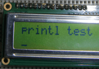
Printl – high level LCD display driver
Some members of this electronic community work with micro-processors. And some of those program them in C/C++.And these people know about the powerful function printf. It is a (built-in) function to produce formatted output to a screen.
Some members of this electronic community work with micro-processors. And some of those program them in C/C++.
And these people know about the powerful function printf. It is a (built-in) function to produce formatted output to a screen.
For those who are not familar with the function, in simple words it is like this;
printf (formatstring, variable1, variable2, …);
The formatstring is a string which characters are output 1 by 1 to the screen, except when a % sign is encountered. The % starts a sequence of characters in the formatstring which describe how a variable is to be presented. As a example “%7.1f” orders a floatingpoint number to be shown, of 7 characters wide and with 1 digit behind the delimeter (.) (And if you want to see a % sign on the screen, you write “%%” in the formatstring).
Credits
This project is indebted to Goofo (see http://www.elektor-labs.com/project/1-pin-uc-interface-for-hd44780-and-compatible-lc-displays-130397-i.13598.html) for his project '1 Pin uC Interface for HD44780 (and compatible) LC Displays [130397-I]' on this elektor-labs website, and to Georges Menie (www.menie.org) for his initial function printf written for the LPC810 in LPCXpresso C.
3-stage project
This project is about using a printf function to send characters to a LCD display. Instead of printf the function is called printl. But for the rest – the parameters – it works the same as printf. Also see the MainSchematic.png picture to understand what happens.
First stage: If you want to use printl, then you have to program a small function printl in your application. Well, for the LPC810, the mbed and the Arduino I have already done that for you. In the software files part of this project you find testprograms for all 3 platforms in which is an implementation of printl and calls to it with all kind of combinations of parameters, to show you how to use printl. What printl actually does is to send the formatstring and variables values to the printl-board by uart. The values are send immediately after a formatting %-sequence. Values are send as 4 bytes data (characters, integers), 8 bytes (floatingpoints, doubles) or strings (ended with '\0').
Second stage: This stage is performed by IC3 on the printl-board. It receives the data of the printl function on it's uart0 and if it is not a %-sequence passes it 1-on-1 on to IC2 by uart1. If it is a %-sequence, it builds the sequence in a makeupstring and reads the valuebytes back in to a correct internal variable. That substring and variable is passed to a printf function, internal in IC3, which outputs the formatted data to uart1 and so on to IC2.
Third stage: This stage is performed by IC2 on the printl-board. By it's uart0 it receives characters from IC3 and outputs them on a GPIO pin using the '1 Pin uC Interface for HD44780 (and compatible) LC Displays' method. It also scans the incoming characters for special ones like TAB ('\t'), BACKSPACE ('\b”), RETURN ('\r') and NEWLINE ('\n'). Those incoming special characters trigger the correct approppriate action to the LCD display. And IC2 also supports a subset of the VT52 terminal protocol ESC sequences. In the other files part of this project you find SupportedControlCharacters.pdf in the zip-file with a list of supported ESC sequences.
Hardware
The hardware is built on a 2-layer PCB with the same dimensions as a Gleichmann 16x2 LCD display. The 16 pins header to the display-board is mounted on the back of the printl-PCB, so that the 2 prints are connected 'back-to-back (B2B)' by this pinheader. Look at the photo's for a impression (better than a 1000 words). Now also look at Schematic-printl.png and PCB-printl.png.
The circuitry around IC1 (74HC595), R1 .. R4, C1 .. C3 and Q1 confirms to the '1 Pin uC Interface for HD44780 (and compatible) LC Displays [130397-I]' design of Goofo (see credits for a link to the elektor-labs website). Note that on the 5-pin connector, apart from +5V and GND, there are connections for 1W and BL. If you want to use the '1 Pin uC Interface' of Goofo, solder these components, together with P1, R5, R8 and T1 on the PCB, and use the PCB for just that. You connect the GPIO output pin of your uC to the 1W pin. You can control the backlight of the LCD screen by setting the BL pin high by another GPIO pin.
But if you want to drive the printl-board by uart TXD (also and a special case of 1-pin interface) solder the rest of the components too (VR1, R6, R7, C6, C7 – for 3V powersupply) and IC2 and IC3. IC2 and IC3 are LPC810M021FN8 uC's of NXP, and must be programmed. IC2 takes over the 1W and BL pin, so you do not connect them anymore on the 5-pin header. On the Schematics you still see Jmp1, but it is no longer there on the PCB-design. You do not need it. All components are through-hole and I advise to use print foots for IC1, IC2 and IC3.
Software
The software that drives the information to the board resides in your uC; the printl function. You can program that function yourself, or if you happen to program a LPC8xx, a mbed supported uC or a Arduino, just copy the function from the software files section of this project. The printl function is small and straight forward. It sends the data in such a way that IC3 can construct the correct textstring. This could be called a protocol.
The protocol is simple; send all characters of the markupstring to the uart, but if you encounter a % sign, look for the designator (s, c, i, d, l, u, x, X, f). Right after sending the designator character, extract the value from the parameter stack and send the value of the variable in the form of bytes.
This is done by the form of a union. A union is a definition of variables in C which resides in the same memory space. They overlap.
So, for example if you extract from the stack a integer of 32 bits, a four bytes array (as_bytes) in the union uses the same memoryspace. If the representaion of a 32 bits integer in both your uC and IC3 is the same, it does not matter how this is send (in this case as four bytes), IC3 is able to recontruct it in a 32 bit integer by using the same union definition.
%c, %i, %d, %l, %u, %x and %X are 32 bit integers, so 4 bytes are send. %s stands for string; the string's characters are send, with a maximum of 16 (the display cannot present more on a single line) and ended with a '\0' character. %f is a 64 bit floating point value; 8 bytes are send.
A note of warning: if you make a mistake in the markupstring and / or in the values or number of variables of a call of C's printf function, the result is unpredicted. It may even hang your program. Printl does not do any better. Sometimes it may be clever to design your program to send information by printf to your screen first (if you have enough program space). After you are finished with that, you simple search/replace 'printf' with 'printl' in your sourcecode.
A special word must be said here about the Arduino Uno. As Arduino truefully admits, in the UNO – the ATMEGA328P – the “double” floatingpoint representation (64 bits) is in fact a 32bit representation. Therefore you will see a #define UNOFLOAT 1 definition in the arduino program. If you use the software not for a Arduino UNO you should set the UNOFLOAT to 0. Special for the UNO the signbit, exponent and mantisse of the 32 bit floatingpoint value are extracted and moved in the approppriate 8 bytes, so that IC3 will present the correct value.
Another important thing to reminder when using a Arduino Uno is that the TxD pin on the 5-pins header (which is connected to the RxD pin of a LPC810) is expected to be of the 3.3V type. Do not connect a 5V powered ATMEGA328P TxD pin to it. If you power the Arduino Uno with 5V "power down" the TxD output by using two resistors to bring it in the 3V range.
IC3
This IC picks up the data send to the printl-board, using it's uart0. The parameters of this serial port are 9600 baud, 8 bits, no parity, 1 stopbit. The uart0 has a interrupt connected to it, so that it can store up to 64 characters in a buffer. This was programmed to be able to send a stream of characters independant of the working speed of IC3. And IC2, with which IC3 has to synchronize in sending of data. What IC3 does is to make new small markupstrings of the overall markupstring of the printl function for each variable and call the local printf function with it and with the value which was send through the bytes. It kind of reverses the action of the printl function. The local printf function was made by Georges Menie, and fits with ease in the 4K flash of the LPC810 (the standard printf function, coming with the REDLIB C compiler is too large – probably a C++ construct, piling heaps of code upon heaps of code).
There are two extensions I made to Georges his function code;
1) the %f is added, supporting floating point numbers
2) the ',' delimeter is added. I explain that. Normal in programming you write a floating point value as, for example 40.1. You instruct printf and printl to do this by %4.1f. It is the anglo-saxon way. But because I am a dutch citizen, I sometimes want it presented as 40,1. IC3 supports this by accepting %4,1f also.
The local printf function outputs via uart1 to IC2.
IC2
The stream of characters generated by IC3 is read by IC2 via it's uart0. Those characters are converted to pulses of the GPIO pin PIO0_3 to drive the 74HC595 chip which drives the data lines on the LCD display.
Mark that to the PIO0_4 output, the RTS of uart0 signal is routed. IC3 has a CTS signal for it's uart1 there. So IC3 and IC2 have a hardware RTS/CTS handshake. I have done this because to generate the pulses for the 74HC595 the IC2 has to go through some time critical functions. It may then not be interrupted. Before entering these time critical functions the interrupts are disabled. If a character from IC3 completes entering in uart0 of IC2 during the period that the interrupts are disabled, it gets lost.
Ready to pick up characters at random intervals is done by IC3 in it's 64 bytes buffer.
Because there still was program memory available, besides generating the pulses, IC2 does some handy character checking. Look back at the top of this article what I wrote at the paragraph 'Third stage' about handling TAB, BACKSPACE, NEWLINE, RETURN and ESCAPE sequences of the VT52 protocol.
I admit that I fizzled on 2 points with the VT52 protocol. First is the ESC = and ESC > sequences. They should change from normal to alternate character set and back. Because there is no alternate character set, what happens is that the cursor is set to blinking or normal.
Second I implemented the unused sequences ESC 1 and ESC 0 (characters one and zero, not values 1 and 0). They switch the backlight of the LCD display on and off.
To program IC2 and IC3 you can use Flashmatic and burn the flash memory with the .hex files which you find in the Release map of the projectfiles in the LPC810-printl-ICs.zip file. If you want to look at (and eventually change) the programs, open a new, blank workspace in LPCXpresso and import the projects from the LPC810-printl-ICs.zip file.
So now I (and you) have a cheap way to drive a LCD display. Apart from the PCB, the costs of the components (about 20 euro's) are much less than buying a LCD display with built-in serial interface.
Build This Project
Bring this design to life with the Elektor PCB Service, powered by Eurocircuits. Upload the project files and order professionally manufactured PCBs or assembled boards through a proven European production platform.
Supporting KiCad, Eagle, Gerber, and ODB++ formats, the service is suitable for everything from prototypes and validation builds to series production and volume manufacturing.
Made in Europe. Fast. Reliable. Professional.
Discussion (1 comment)