
RGB color mixer using Arduino
the RGB LED color mixer is a project that is suitable for the beginner Arduino users who is interested in building an interactive gadget to mix colors.
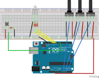
The simple circuit combines three potentiometers to set brightness for each of the given green, red and the blue LEDs located inside the RGB LED. A switch button is used to turn the circuit on and off.
Components:
Arduino Uno
RGB LED
Resistor 10K ohm
Resistor 221 ohm
Jumper wires
Pushbutton switch
Breadboard
Rotary potentiometer.
Procedure:
You have to wire the schematic as shown in the diagram. Wire the RGB LED in the PMW pins 9,10 and 11 of the Arduino.
Connect the pushbutton to pin 7 .
Connect the three potentiomete2 into pin A0, A1 and A3 respectively
Add a 10Kilo-Ohms resistor to the ground connected to the pushbutton.
Connect the three 230 ohm resistors between the LEDs and the output pins to protect the LEDs from blowing off.
Operation:
After wiring the schematic listed, try turning the potentiometers knob. Nothing happens because the pushbutton is off. Hit the pushbutton and try turning the knobs again and now the LED should turn on. You notice different colors depending on which LED is on or off or partially on.
Code:
int blue = 9; // Define Digital Pins for each colour of the LED

int green = 10;

int red = 11;


int redPot = A0;

int greenPot = A1; //Define Analog Pins for the 3 potentiometers

int bluePot = A2;


int greenVal = 0; //Create a variable to store the state of each Potentiometer

int blueVal = 0;

int redVal = 0;


const int BUTTON = 7; //Define the button Pin

int state = 0;    //Create a variable to store wether button is on or off

int val = 0;      //Create a variable to store the momentary state of the button

int old_val = 0;  //create a variable to store the previous state of the button


void setup() {

  // put your setup code here, to run once:


  pinMode(green, OUTPUT);  //Set LED's as output's, button as input

  pinMode(blue, OUTPUT);

  pinMode(red, OUTPUT);

  pinMode(BUTTON, INPUT);

  Serial.begin(9600);

}


void loop() {

  // put your main code here, to run repeatedly:

  Serial.begin(9600);                       //Open the serial monitor at 9600 baud


  val = digitalRead(BUTTON);                // Check state of button


  if ((val == HIGH) && (old_val == LOW)) {  //Check to see if state of button has changed

    state = 1 - state;                      //Set the button as either on (1) or off (0)

    delay(10);

  }


  old_val = val;                            // Save the previous button reading to compare next time through loop


  greenVal = analogRead(greenPot);          //Read the position of the potentiometers

  blueVal = analogRead(bluePot);

  redVal = analogRead(redPot);


  if (state == 1) {                         //If button is on, set the state of each LED according to position

    analogWrite(green, greenVal / 4);       //of its correspoding potentiometer. Anolog inputs range from 0-1023,

    analogWrite(blue, blueVal / 4);         // while anolog outputs as PMW can be from 0-255. Therefore we must

    analogWrite(red, redVal / 4);           // divide the potentiometer readings by 4 to set the state correctly


    Serial.print("RGB(");

    Serial.print(redVal/4);

    Serial.print(",");

    Serial.print(greenVal/4);

    Serial.print(",");

    Serial.print(blueVal/4);                 //Print the RGB Code, resuable in any RGB application

    Serial.println(")");


    delay(50);

  } else {                                   // If button is off, set all LED's to LOW/off

    analogWrite(green, 0);

    analogWrite(blue, 0);

    analogWrite(red, 0);

    delay(50);

  }

}
Want to build a project?
Bring your design to life with the Elektor PCB Service, powered by Eurocircuits. Upload the project files and order professionally manufactured PCBs or assembled boards through a proven European production platform.
Supporting KiCad, Eagle, Gerber, and ODB++ formats, the service is suitable for everything from prototypes and validation builds to series production and volume manufacturing.
Made in Europe. Fast. Reliable. Professional.
Discussion (0 comments)