
Simple AVR ATtiny13 based PWM generator
Missing a simple PWM generator for a project? The Simple AVR ATtiny13 based PWM generator is your solution. It contains 4 parts, only.
For another project I wanted to test an LED array designed for an underwater LED lamp. The LED array consists of 10 red CREE XP E2 LEDs (75 lm / 1 W each) and 5 warm white Cree XM-L LEDs (220 lm / 3 W each). The LED array is mounted on a 53 mm diameter / 35 mm high aluminium block.
In special I wanted to measure the impact of the PWM duty to LED voltage and power dissipation / temperature of the aluminium block. The underwater LED project shall be realizes with an AVR ATtiny44 chip. This defines the PWM capabilities for the LED driver.
For testing in advance I designed an ATtiny13 based simple PWM generator which runs at 9.6 MHz with system clock prescaler fuse off. In Fast PWM mode the possible frequencies for the PWM signal do calculate using the equation
F(PWM) = F(CPU) / (N * 256)
with N as timer prescaler with possible values
- 1 => 37.500 kHz
- 8 => 4.6875 kHz
- 64 => 586.0 Hz
- 256 => 146.48 Hz
- 1024 => 36.62 Hz
The duty cycle is set by a 8 bit counter with values 0...254.
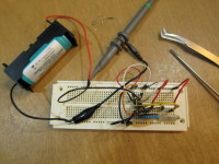
As simple input devices for frequency and duty I chose two potentiometers at two ADC inputs. The ADCs are set to utilize Vcc as reference. Looking into my potentiometer collection I found two trim pots (from Pollin) with a control reel (see breadboard-poti.jpg). The resistance value is not critical. I tried a 1 kOhm pot as well as a 100 kOhm pot.
The duty pot R1 (see Eeschema.png) showed to be too coarse for a fine resolution duty setting. So I replaced it by a spindle pot giving the wanted resolution.
The freq pot R2 (see Eeschema.png) has to cover the 5 settings for the PWM timer prescaler values. No problem with resolution.
Testing the simple PWM generator on a breadboard shows very good results near to the calculated PWM frequencies:
- 37.500 kHz (calc) / 38.1 kHz (real)
- 4.6875 kHz (calc) / 4.73 kHz (real)
- 586.0 Hz (calc) / 594 Hz (real)
- 146.48 Hz (calc) / 148 Hz (real)
- 36.62 Hz (calc) / 37.1 Hz (real)
The duty ranges from 0.4 % to 99,6 % (see attached images).
Component list:
Ref	Value
C1	100n
J1	Power
J2	PWM out
J3	PWM out
R1	2k2
R1'	spindle
R2	10k
U1	ATtiny13V-10PU
Attachments:
- breadboard-poti.jpg
- breadboard-spindle.jpg
- LabNation_Screenshot*.png
- Eeschema.png
- Code-pwmGenerator-attiny13.zip
- KiCad-pwmGenerator-attiny13.zip
Build This Project
Bring this design to life with the Elektor PCB Service, powered by Eurocircuits. Upload the project files and order professionally manufactured PCBs or assembled boards through a proven European production platform.
Supporting KiCad, Eagle, Gerber, and ODB++ formats, the service is suitable for everything from prototypes and validation builds to series production and volume manufacturing.
Made in Europe. Fast. Reliable. Professional.
Discussion (0 comments)