
STM32L476 RTC Clock
In this project we learn in detail how to use the RTC (real-time clock) from the STM32L476, create fonts, bitmap and use the oled W click from MIKROE as display. The purpose is to make custom instrument display. Also to create a tool in calc (linux) or exel (MS-windows) which can transfer from pixel to hexcode.
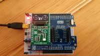
OLED W click from MIKROE 20.40 €
Arduino click SHIELD from MIKROE 6.40 €
STM32 NUCLEO-L476RG from ST availaible in the Elektorshop 24.95 €
STM32CubeIDE 1.6.1 or later free (after registration).
Total cost 51.95 €
Preparation We will use the I2C bus for OLED W. The jumpers J1, J2 and J3 must be on the I2C position. Put the Arduino click SHIELD on the NUCLEO-L476RG and the OLED on the left side of the Arduino click SHIELD. Note: every module works on 3.3V (not 5V like the Arduino UNO)
Start IDE File New STM32 Project Follow the datasheet from the OLED driver Solomon SSD1306 page 15 and 20
Configuration For the OLED we need SCL = PC0
SDA = PC1
D/C = PB10
RES = PB0
CS = PB6
Add in core Inc the files fonts.h and ssd1306.h and Bitmaps.h
Add in core Src the files fonts.c and ssd1306.c
How to create fonts
I want to create fonts 12 pixels wide and 18 high. We use uint16_t, which means 16 bits. To keep it short use Hexcode. STM32 reads the font from upperside of 16 bits, 18 times in our example. We only need number characters but it is necessary to start with the space symbol and the 15 characters that follow, will go untill character zero. Because we don’t use them, we have to fill up with zero.
const uint16_t Font12x18 [] =
{
0x0000, 0x0000, 0x0000, 0x0000, 0x0000, 0x0000, 0x0000, 0x0000, 0x0000, 0x0000, 0x0000, 0x0000, 0x0000, 0x0000, 0x0000, 0x0000, 0x0000, 0x0000, // space
}
This array we put in file fonts.c for all the characters we need and it must be in the correct order like the asci table. Below we put the font definition also in file fonts.c
FontDef_t Font_12x18 = { 12, 18, Font12x18 }; Need to add the folowing in file fonts.c
/**
* @brief 12 x 18 pixels font size structure
*/
extern FontDef_t Font_12x18;
To help creating the hex codes for the fonts, I have made “font template.ods” in the tab “STM32 fonts”. For changing: you add or delete char “1” in the cell. With the formule =DEC2HEX((E1*1)+(D1*2)+(C1*4)+(B1*8)) we create the hex codes. If done, copy and paste it in your array.
How to make a bitmap
Our display is 128 pixels wide and 38 pixels deep. In “font template.ods”, tab “ssd1306_bitmap”, you find an example 96 colums wide and 32 rows deep. On the right side you find the hex code same way as before: =DEC2HEX((E1*1)+(D1*2)+(C1*4)+(B1*8)). The bitmap is uint8_t. Insert char “1” in the cell to light up or delete to remove.
Moving clock-hand
We make an analog clock (or an instrument) that needs fast moving clock-hand. We can calculate the place and direction in the program, but the purpose is that the processor needs to calculate sensor value, filter and so on. To make it easy and fast, it will be better if we calculate the position from the clock-hand and put it in a switch. Our example: the clock = circle 360 degrees devided by 60 minutes (or seconds) is 6 degrees. In the spreadsheet “font template.ods”, tab “coordinate x y 60 parts”, we calculate the x and y from the start and x and y from the end position like:
SSD1306_DrawLine(107, 44, 103, 44, 1); At the end we put the color, 1 is white, 0 for black.
The length of the line is 12 pixels. The formule:
=12*SIN(RADIANS(B2)) for X =12*COS(RADIANS(B2)) for Y Convert the corner in degrees to “Open Office” radians and later we add the X Y offset for the display because the upper side left corner of the display is not 0,0 but 32,25.
The main.c
Open the main.c in the Src add the include between the user code:
/* USER CODE BEGIN Includes */ #include "fonts.h" #include "ssd1306.h" #include#include "Bitmaps.h" /* USER CODE END Includes */
*If you put this code on another place, then it will be cleaned up after compiling the ****.ioc file.
Write the private variable:
/* USER CODE BEGIN PV */
char time[10];
char date[10];
char second[4];
/* USER CODE END PV */
Define the variable gDate and gTime:
/* USER CODE BEGIN 1 */
RTC_DateTypeDef gDate;
RTC_TimeTypeDef gTime;
/* USER CODE END 1 */
Initialize the peripherals:
/* Initialize all configured peripherals */
MX_GPIO_Init();
MX_USART2_UART_Init();
MX_RTC_Init();
MX_I2C3_Init();
The user code:
/* USER CODE BEGIN 2 */
// Make the ssd1306 ready to display datasheet page 15 and 20

HAL_GPIO_WritePin(GPIOB, GPIO_PIN_0, GPIO_PIN_RESET); //RST write (port, pin, status)
HAL_Delay(10);
HAL_GPIO_WritePin(GPIOB, GPIO_PIN_0, GPIO_PIN_SET); //RST write (port, pin, status)
HAL_Delay(5);
HAL_GPIO_WritePin(GPIOB, GPIO_PIN_10, GPIO_PIN_RESET); //DC for command lines
HAL_Delay(5);
HAL_GPIO_WritePin(GPIOB, GPIO_PIN_6, GPIO_PIN_SET); //CS for command lines HAL_Delay(5);
SSD1306_Init();
SSD1306_Contrast(50);
SSD1306_GotoXY(32, 25);
SSD1306_Puts("123456789012345", &Font_6x8, 1); //fillup the display for test
SSD1306_GotoXY(32, 32);
SSD1306_Puts("abcdefghijklmno", &Font_6x8, 1); //fillup the display for test
SSD1306_GotoXY(32, 39);
SSD1306_Puts("pqrstuvwxyz;=@#", &Font_6x8, 1); //fillup the display for test
SSD1306_GotoXY(32, 47);
SSD1306_Puts("ABCDEFGHIJKLMNO", &Font_6x8, 1); //fillup the display for test
SSD1306_GotoXY(32, 55);
SSD1306_Puts("PQRSTUVWXYZ1234", &Font_6x8, 1); //fillup the display for test
SSD1306_UpdateScreen();
HAL_Delay(5000); //wait 5 seconds SSD1306_Clear(); //clear the display
/* USER CODE END 2 */
The loop first part digital clock with futuristic fonts. Make sure that the clock changes every second and shows the time for 50 times 100ms = 5 seconds + time to run the commands. Ask the time and date and put it in the array. The Weekday starts with number; 0 for Sunday. We must cast it to a string with a switch .
/* Infinite loop */
/* USER CODE BEGIN WHILE */
while (1)

{
  for(int delay = 0; delay < 50; delay++) // Digital clock
  {
    HAL_RTC_GetTime(&hrtc, &gTime, RTC_FORMAT_BIN);
    /* Get the RTC current Date */
    HAL_RTC_GetDate(&hrtc, &gDate, RTC_FORMAT_BIN);
    /* Display time Format: hh:mm:ss */

sprintf((char*)time,"%02d:%02d:%02d",gTime.Hours, gTime.Minutes, gTime.Seconds);
    sprintf((char*)date,"%02d-%02d-%02d",gDate.Date, gDate.Month, 2000 + gDate.Year);
    SSD1306_GotoXY(31, 30);
    SSD1306_Puts( time, &Font_12x18, 1);
    SSD1306_GotoXY(38, 55);
    switch(gDate.WeekDay) //days of week Monday = 1
    {
       case 0:
         SSD1306_Puts("Sun", &Font_6x8, 1);
       break;
       case 1:
         SSD1306_Puts("Mon", &Font_6x8, 1);
       break;
       case 2:
         SSD1306_Puts("Tue", &Font_6x8, 1);
       break;
       case 3:
         SSD1306_Puts("Wed", &Font_6x8, 1);
       break;
       case 4:
         SSD1306_Puts("Thu", &Font_6x8, 1);
       break;
       case 5:
         SSD1306_Puts("Fri", &Font_6x8, 1);
       break;
       case 6:
         SSD1306_Puts("Sat", &Font_6x8, 1);
       break;
    }
    SSD1306_GotoXY(62, 55);
    SSD1306_Puts( date, &Font_6x8, 1);
    SSD1306_UpdateScreen();
    HAL_Delay(100);
}
The second part is how put the analog clock on the display
First, clear the digital clock on the display. Ask the time again and in the middle I put the seconds. On the left side draw the clock-hand, the line starts in the centre of the clock and it is 12 pixels long. (See spreadsheet). We use I2C at 400KHz for the display but if we clear the display every update, it gives an annoying picture. So it’s better without clearing but redraw the last line “black” before draw the new line.
SSD1306_Clear();
for(int delay = 0; delay < 100; delay++) // Analog clock
{
   HAL_RTC_GetTime(&hrtc, &gTime, RTC_FORMAT_BIN);
   HAL_RTC_GetDate(&hrtc, &gDate, RTC_FORMAT_BIN);
   SSD1306_GotoXY(75, 45);
   sprintf((char*)second,"%02d",gTime.Seconds);

switch(gTime.Seconds) //second arrow
   {
      case 0:
        SSD1306_DrawLine(49, 44, 48, 32, 0); //59 make arrow black
        SSD1306_DrawLine(49, 44, 49, 32, 1); //00 white arrow
      break;
code continue
   switch(gTime.Minutes) //Minutes arrow
   {
     case 0:
       SSD1306_DrawLine(110, 41, 109, 32, 0); //59 make arrow black
       SSD1306_DrawLine(110, 41, 110, 32, 1); //00 white arrow break;
code continue
It is different for the hour arrow. We have only 12 hours, so we must multiply by 5 for a scale of 60. Because we have also 24 hours, we check if the result is bigger or equal to 60. If yes, the result will be decreased by 60. But if the minutes run, need to add this also to the hour arrow. Devide the minutes by 12. From one hour to the next is 5 scales or 30 degrees, 360 degrees divided by 30 is 12. To give a fancy appearance we don’t start drawing from the centre of the clock but 4 pixels away from the centre.
int hour;
if (((gTime.Hours)*5)>=60) //if hour > 12 then -12 (hour *5 for 60 devisions)
{
   hour = (((gTime.Hours)*5)-60)+((gTime.Minutes)/12); //add the minutes also }
else
{
   hour = ((gTime.Hours)*5)+((gTime.Minutes)/12);
}
switch(hour) //Hour arrow
{
   case 0:
      SSD1306_DrawLine(110, 41, 109, 37, 0); //59 make arrow black
      SSD1306_DrawLine(110, 41, 110, 37, 1); //00 white arrow
   break;
code continue
Write the seconds in the middle, one bitmap left and draw the same right (x+61). The clock-hands are also x+61 pixels to the right side:
  SSD1306_GotoXY(68, 45);
  SSD1306_Puts( second, &Font_12x18, 1); // Seconds in digit in the middle
  SSD1306_DrawBitmap(33,29, clockscreen, 96, 32, 1); //clock frame left
  SSD1306_DrawBitmap(94,29, clockscreen, 96, 32, 1); //clock frame right
  SSD1306_UpdateScreen();
  HAL_Delay(100);
}
SSD1306_Clear(); //00 clear to show digital clock
Note about the ssd1306 display. In writing text on the display, the X Y must be 128 and 64 for the driver. If it mentions 32 for Y you get a black line between each written line. But for your bitmap, the size of the display is 96 and 38. It is possible to draw on 0/0 but you need to scroll the picture to make it visible.
x=32/y=25 96 pixels x=128/y=25
**********************************
* ssd1306 display * 38 pixels
**********************************
x=32/y=63 x=128/y=63
Finally the RTC. When start the project, configure the RTS. I set already some values. The time will also show when it starts up. However, each time you boot the STM it will take the hours mentioned below in the backup code. The board needs a backup battery or supercap from 1F in serie with 33 ohm resistance. The jumper SB45 must be replaced by a diode.
To set the time in the program, adjust sTime.Hours = 0x10; sTime.Minutes = 0x50; also sDate.WeekDay = RTC_WEEKDAY_SATURDAY; sDate.Month = RTC_MONTH_AUGUST; sDate.Date = 0x07 and sDate.Year = 0x21;
For code suggestions press Ctrl and spacebar together.
/** Initialize RTC Only
*/
hrtc.Instance = RTC;
hrtc.Init.HourFormat = RTC_HOURFORMAT_24;
hrtc.Init.AsynchPrediv = 127;
hrtc.Init.SynchPrediv = 255;
hrtc.Init.OutPut = RTC_OUTPUT_DISABLE;
hrtc.Init.OutPutRemap = RTC_OUTPUT_REMAP_NONE;
hrtc.Init.OutPutPolarity = RTC_OUTPUT_POLARITY_HIGH;
hrtc.Init.OutPutType = RTC_OUTPUT_TYPE_OPENDRAIN;
if (HAL_RTC_Init(&hrtc) != HAL_OK)
{
   Error_Handler();
}
/* USER CODE BEGIN Check_RTC_BKUP */
/* USER CODE END Check_RTC_BKUP */
/** Initialize RTC and set the Time and Date
*/
sTime.Hours = 0x10;
sTime.Minutes = 0x50;
sTime.Seconds = 0x0;
sTime.DayLightSaving = RTC_DAYLIGHTSAVING_NONE;
sTime.StoreOperation = RTC_STOREOPERATION_RESET;
if (HAL_RTC_SetTime(&hrtc, &sTime, RTC_FORMAT_BCD) != HAL_OK)
{
   Error_Handler();
}
sDate.WeekDay = RTC_WEEKDAY_SATURDAY;
sDate.Month = RTC_MONTH_AUGUST;
sDate.Date = 0x07;
sDate.Year = 0x21;
if (HAL_RTC_SetDate(&hrtc, &sDate, RTC_FORMAT_BCD) != HAL_OK)
{
   Error_Handler();
} Want to build a project?
Bring your design to life with the Elektor PCB Service, powered by Eurocircuits. Upload the project files and order professionally manufactured PCBs or assembled boards through a proven European production platform.
Supporting KiCad, Eagle, Gerber, and ODB++ formats, the service is suitable for everything from prototypes and validation builds to series production and volume manufacturing.
Made in Europe. Fast. Reliable. Professional.
Discussion (0 comments)