
STRESS FREE AUTOMATED VEHICLE TURN SIGNAL WITH ESP8266 AND MPU6050
The goal of this project is to switch the vehicle turn signal right/left bulbs by itself and the driver is all free from the stress. Using MPU6050 six axis gyrometer cum accelerometer it is made possible to find the direction of movement of the four wheeler’s steering wheel or a two wheeler’s handle bar.
Description:
The existing manual indicator switching system is to be combined with our project. i.e The system operates in both manual and automated mode. The operation of the system is as follows,
1. Manual mode – The regular operation is carried out with respect to switching Left/ Right. This is used when the driver needs to switch on the indicators prior to turning the vehicle or when required.2. Automated mode – When the four wheeler’s steering or two wheeler’s handlebar is tilted towards left, then the left indicator lamp gets switched on and the same for right side. A).Corrective mode – When the driver switches the wrong side indicator, i.e switches left indicator and turns towards the right, the system bars the manual mode and switches the right indicator.
Bill of Materials:
Programme Code Explanation.
In setup function, serial communication is initialized, setup MPU6050 sensor and defines the pins used for RELAY as Output pins.
In loop function,
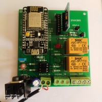
Construction and Testing:
Connect the sensor according to the given circuit diagram, upload the code to the board, and power the device with USB cable or 5V battery. Now make change in the position of the prototype wheel. The corresponding relay gets switched on.
The existing manual indicator switching system is to be combined with our project. i.e The system operates in both manual and automated mode. The operation of the system is as follows,
1. Manual mode – The regular operation is carried out with respect to switching Left/ Right. This is used when the driver needs to switch on the indicators prior to turning the vehicle or when required.2. Automated mode – When the four wheeler’s steering or two wheeler’s handlebar is tilted towards left, then the left indicator lamp gets switched on and the same for right side. A).Corrective mode – When the driver switches the wrong side indicator, i.e switches left indicator and turns towards the right, the system bars the manual mode and switches the right indicator.
Bill of Materials:
- | ESP8266 NODEMCU(MOD1) | Microcontroller for programming
- | MPU6050(MOD2) | 6-axis gyro and accelero sensor
- | Micro USB | For programming
- | Breadboard | For circuit prototyping
- | Resistors - 330R | Used as base resistor for transistor
- | Resistors - 4K7 | Pull down for input pins
- | Left right on / off switch (we can use existing vehicle switch) | To switch between Left & Right direction
- | Transistor BC547 | To switch relays
- | 12 V DPST Relay | To operate the right/left Indicator lamps
- | Diode 1N4007 | Used in relay circuit
Programme Code Explanation.
In setup function, serial communication is initialized, setup MPU6050 sensor and defines the pins used for RELAY as Output pins.
In loop function,
- 1.The accelerometer and gyrometer values are read in 3 axis.
- 2. Since it is all about rotation, we take GyY and process further.
- 3.Min speed is the least speed at which the rotation is to be considered and Max value is division of 360 degree. Here I have use 10 as min speed and 12 as maximum value for my prototyping.
- 4.If the read value comes under the specified speed, then the value is moved to curr_y. The curr_y is saved in last_y before leaving the loop.
- 5.Using the curr_y, the curr_val is determined.
- 6.Based on the curr_val, it is found whether the four wheeler’s steering wheel or a two wheeler’s handle bar is moved in right or left and switches the corresponding Relay.
Construction and Testing:
Connect the sensor according to the given circuit diagram, upload the code to the board, and power the device with USB cable or 5V battery. Now make change in the position of the prototype wheel. The corresponding relay gets switched on.
Build This Project
Bring this design to life with the Elektor PCB Service, powered by Eurocircuits. Upload the project files and order professionally manufactured PCBs or assembled boards through a proven European production platform.
Supporting KiCad, Eagle, Gerber, and ODB++ formats, the service is suitable for everything from prototypes and validation builds to series production and volume manufacturing.
Made in Europe. Fast. Reliable. Professional.
Discussion (0 comments)