


Three Input-Eight-Output Decoder Simulation Using Ni Multisim EDA
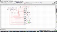
In this project am going to show you how you can simulate a three-line-input eight-line-output decoder using the NI Multisim EDA.
I made a design of the three-line input to eight-line output combination circuit. This in real sense forms the 3- to -8 -line decoder. From the circuit designed through the NI Multisim, I can note that the inputs are represented through A, B and C while the outputs are represented by the U4, U5, U6, U7, U8, U9, U10 and U11. The circuit is made up of 8 AND and 3 NOT gates. Here we can do the selection of the eight outputs based on the three given inputs and therefore we can have the truth table that is shown below. From the given truth table we can note that one of the outputs can be selected at any given single input. From the truth table of the 3 line to 8 line of our combination logic, the logic expressions can be define as;
Components:
1. AND gate
2. NOT gate
3. Probe-Dig- Green
4. Toggle Key
Expected Combinations:Y0=A’B’C’
Y1=A’B’C
Y2=A’BC’
Y3=A’BC
Y4=AB’C’
Y5=AB’C
Y6=ABC’
Y7=ABC
This can only be made possible by the help of these logic gates and 8-three input AND gates. Apart from having three inputs and eight outputs, the decoder must have one enable pin as shown in the combination circuit where E represents the enabling key.
See attached documents for more information.
Want to build a project?
Bring your design to life with the Elektor PCB Service, powered by Eurocircuits. Upload the project files and order professionally manufactured PCBs or assembled boards through a proven European production platform.
Supporting KiCad, Eagle, Gerber, and ODB++ formats, the service is suitable for everything from prototypes and validation builds to series production and volume manufacturing.
Made in Europe. Fast. Reliable. Professional.
Discussion (0 comments)