
Two Potentiometers on One Digital Input
Connect two potentiometers on one digital microcontroller input.
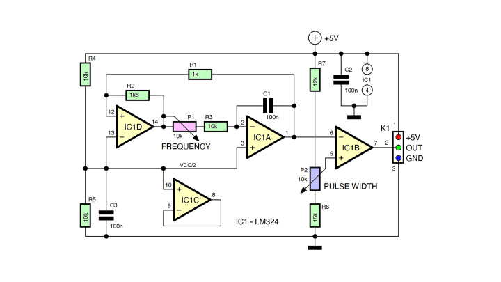
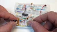
The circuit shown here can generate the kind of signal we are looking for. It is a classic opamp-based triangle/rectangle wave oscillator. Note that you can use any other type of oscillator capable of producing a rectangle wave with variable frequency and duty cycle. In this project the highlight of the show is not in the circuit, but in what we do with it.
The output of IC1A is a triangle wave. Potentiometer P1 controls its frequency. The value of P1 sets the minimum frequency, R3 fixes the maximum frequency. The frequency is, of course, also determined by C1. With the given component values, I obtained a range from about 250 Hz to 500 Hz, easy-peasy for a microcontroller.
IC1B compares the triangle wave with the voltage set by P2, R6 and R7. The result is a rectangle signal with a duty cycle controlled by P2. With the given component values, the duty cycle can be adjusted from about 10% up to 90%. By tweaking R6 and R7, you can modify the range. Ideally, they would have identical values, but as the triangle wave is not perfectly centered around half the supply voltage, they are slightly different.
IC1C is not used and stored away in a good way for unused opamps. C2 and C3 are supply decoupling capacitors.
Software
The software required to decode the modulated rectangle signal can remain quite simple. As usual there are several approaches possible. The method I used is to make the main loop check the signal every once in a while. There is no point in doing this at a super high rate, every 10 ms or so is good enough. Then the program waits for a level change or edge of the signal to occur. Always use the same edge, of course. I chose a rising edge.The obtained values are slightly imprecise due to mainly potentiometer noise, and so you may want to apply some filtering.
The same algorithm can be implemented using interrupts, which allows it to be run as a background task. This leaves the main loop free for doing other things.
Three Potentiometers?
Now you may say, why not also add amplitude modulation to the rectangle signal? Then you can have three potentiometers instead of two! Well, you can do this, of course, but then you would need an analog input on the microcontroller and our objective was to not use an analog input.
More Than Just a Trick
The technique presented here is more than just a trick or curiosity. As the information is transported in binary form over a single wire, it is noise resistant and allows for long distances between the potentiometers and the microcontroller. Furthermore, it is easy to add galvanic isolation. This is great for e.g. medical applications, or to control in a safe way a system that is directly connected to the mains. It can also operate over an infrared link, giving you remote control.
More Details in This Video
Want to build a project?
Bring your design to life with the Elektor PCB Service, powered by Eurocircuits. Upload the project files and order professionally manufactured PCBs or assembled boards through a proven European production platform.
Supporting KiCad, Eagle, Gerber, and ODB++ formats, the service is suitable for everything from prototypes and validation builds to series production and volume manufacturing.
Made in Europe. Fast. Reliable. Professional.
Discussion (1 comment)