Battery Checker
One to ten cells, up to 10 A

This is a MEMBER ONLY article. You need a subscription to read this article.
- Unlimited access to online Member Only articles
- 3 new editions Elektor Magazine (digital)
- More than 5000 Gerber files
- 20% member discount on e-books (at elektor.com)
- 10% member discount on Products (at elektor.com)
Available from €5.33 per month.
What is Members Only
Elektor is committed to providing high-quality content on electronics, catering to tens of thousands of paying members. As part of this commitment, Elektor has launched Premium, an initiative that offers exclusive online articles to members sometimes even before they appear in the magazine.
Every day, members can access in-depth articles that showcase the best of Elektor's premium content.
This initiative aims to reward members with early access. Once logged in, members can easily enjoy this exclusive content and engage in discussions about featured projects. While Premium adds to the existing resources available, Elektor will continue to provide a wealth of free information.
Join the Elektor community today to take advantage of Premium and other benefits!
Materials
Gerber file
CAM/CAD data for the PCB referred to in this article is available as a Gerber file. Elektor GREEN and GOLD members can exclusively download these files for free as part of their membership. Gerber files allow a PCB to be produced on an appropriate device available locally, or through an online PCB manufacturing service.
Elektor recommends the Elektor PCB Service service from its business partner Eurocircuits or AISLER as the best services for its own prototypes and volume production.
The use of our Gerber files is provided under a modified Creative Commons license. Creative Commons offers authors, scientists, educators and other creatives the freedom to handle their copyright in a more free way without losing their ownership.
Extra info / Update
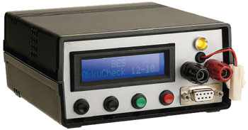
Voltage range 0 V to 12 V (corresponding to 0 to 10 NiCd or NiMH cells)
Discharge current up to 10 A
Internal resistance measurement at the start of the discharge process (average of ten readings)
Constant current discharge with switch-over to constant voltage discharge
Display of set-point and actual values of voltage and current
Display of discharge time, total charge, internal resistance, heatsink temperature and fan speed
Controlled using four pushbuttons to set cell count, required discharge termination voltage and required discharge current
Calibration facility for A/D converter and current regulator PWM
Backlit 2-by-16 character LCD
Status LED
Heatsink temperature monitoring with fan control (proportional controller)
Serial interface to output values and to receive control messages
Maximum power dissipation 120 W (with special cooling), adjustable 40 W limit in software
Free download of software and printed circuit board layouts at 071131
Component list
(5%, 0.25W unless otherwise indicated)
R1–R4, R6–R10, R15,R16,R17, R19, R21–R24, R26–R29, R33 = 10kOhm
R5 = 4.02kOhm (1%)
R11,R12,R18,R31,R40 = 1kOhm
R13 = 2.2kOhm
R14, R30, R39 = 150Ohm
R20, R25 = 2.49kOhm (1 %)
R32, R36 = 47kOhm
R34 = 100Ohm
R35 = 5.6kOhm
R37 = 470Ohm
R38 = 50mOhm 0.5 % precision power resistor, e.g. Isabellenhütte Heusler type PBV 0.05 (Conrad Electronics # 447382-62)
P1 = 10kOhm preset, horizontal
P2 = 2.5kOhm preset, vertical
Capacitors
C1 = 1000µF 63V radial, lead pitch 10mm
C2,C4,C6, C9–C12 = 100nF 50V ceramic
C3,C5,C7 = 47µF 25V radial, lead pitch 0.1 inch
C13–C17 = 1µF 16V radial, lead pitch 0.1 inch
C8,C18,C19,C21 = 10nF ceramic
C20 = 100µF 16V, radial, lead pitch 0.2 inch
Inductors
L1 = 100 µH miniature choke (resistor body)
Semiconductors
B1 = DB104G (Taiwan Semiconductor), 1A 400V bridge rectifier (e.g. Farnell # 706796)
D1 = LT1009CLPG4 (TI), 2.5V voltage reference, TO-92 case (e.g. Farnell # 9589724)
D2 = 1N4004
IC1 = 7805 with 15 K/W heatsink
IC2 = 7810
IC3 = 7812
IC4 = TLC274BCN (TI), DIP-14 with socket
IC5 = ATmega32-16PU (ATMEL), DIL-40 with socket, programmed, order code 071131-41*
IC6 = MAX232N (TI), DIP-16 with socket
T1,T2,T3 = BC337-40
T4 = IRFP064NPBF (International Rectifier, e.g. Farnell # 8649227)
T5 = BD679
Miscellaneous
K1 = 2-way PCB screw terminal, lead pitch 7.5mm
K2,K3,K8,K9 = 2-pin pinheader, 0.1 inch lead pitch
K4 = 3-pin pinheader, 0.1 inch lead pitch
K5 = 16-way (2x8) pinheader, 0.1 inch lead pitch
K6 = 10-way (2x5) pinheader, 0.1 inch lead pitch
K7 = 2 solder pins, 1.3mm diam.
LCD1 = 2x16 characters, e.g. DEM16217 SYH-PY /V (Elektor-Shop # 030451-72)
TR1 = PCB transformer, 12V 0.33A secondary, e.g. EI38/13.6 4.0 VA (Pulse), part no.: 038-5414.0 (230V primary), 038-5402.0 (115V primary) or HAHN type BV EI 382 1191 (230V primary)
X1 = 8MHz quartz oscillator module, e.g. AEL Crystals type O8M000000L642 (Farnell # 9509712)
X2 = 32.76 kHz watch crystal, cylindrical case
F1 = fuse 0.315A 250V, slow blow, dim. 5x20mm, incl. fuseholder and cap
F2, F3 = fuse 6.3A fast, dim. 5x20mm, incl. fuseholder
9-way sub-D socket
4 pushbuttons for front panel mounting
Fan, 12VDC, 80mA, dim. 40x40mm
KTY 81-122 (NXP), PTC temperature sensor, SOD-70 case
Heatsink, Fischer Elektronik type SK 68/50 SA, dim. 50x46x33mm, rating 4.6K/W
Bicolor LED (green/red), 5mm diam.
Heat conducting glue for securing temperature sensor to heatsink
Terminal posts, 4mm diam. (1 red, 1 black)
PCB nos. 071131-1* (PSU) and 071131-2* (main board)
* Kit of parts no. 071131-71 containing PCBs, a programmed microcontroller and all parts (except case)
Discussion (0 comments)