Article
Experimental Doppler Radar
or how to build your own speed trap

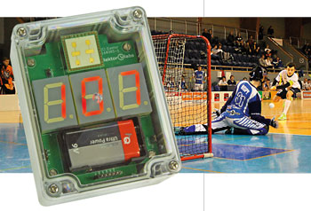
A couple of years ago I read an article about small radars. After that I also began noticing product news items from various companies about small, low-cost radar transceiver chips and modules, and so I decided to do a hobby project on microwave radar. Here’s what I came up with.The aim of the project was to build a microwave Doppler radar by using an, low-cost off the shelf radar module. The most interesting thing as I see it was to learn new things and make electronics bits and pieces work as planned.
Gerber file
CAM/CAD data for the PCB referred to in this article is available as a Gerber file. Elektor GREEN and GOLD members can exclusively download these files for free as part of their membership. Gerber files allow a PCB to be produced on an appropriate device available locally, or through an online PCB manufacturing service.
Elektor recommends the Elektor PCB Service service from its business partner Eurocircuits or Eurocircuits as the best services for its own prototypes and volume production.
The use of our Gerber files is provided under a modified Creative Commons license. Creative Commons offers authors, scientists, educators and other creatives the freedom to handle their copyright in a more free way without losing their ownership.
PCB
Extra info / Update
Features
* Measures speed of moving targets
* Commercially available low power radar module
* K-band (24 GHz)
* Range 60 m minimum; 100 m usable
* Resolution 0.24 m/s
* Easy-to-understand digital signal processing
* Universal dsPIC baseboard can be repurposed for other applications
@ www.elektor.com
- Experimental Doppler Radar, bare PCB www.elektor.com/doppler-radar-pcb
- dsPIC33EP128GP502, programmed www.elektor.nl/doppler-radar-dspic
- K-LC5 Doppler radar transceiver www.elektor.com/k-lc5
Component list
Component List
Resistors
R28,R42 = not fitted*
R5-R11,R23,R24,R36,R38,R40 = 1kohm
R12 = 2kohm
R1-R4,R13-R20,R29*,R30,R31,R34,R35,R37,R39,R41,R44* = 10kohm
R25 = 20kohm
R43* = 31.6kohm
R27 = 64.9kohm
R21,R22,R33 = 100kohm
R32 = 180kohm
R26 = 210kohm
Capacitors
C17 = 1nF
C2,C3,C4,C5,C8,C16,C19* = 100nF
C1 = 1µF 16V
C6,C7,C9,C10,C13,C14 = 2.2µF 16V
C11,C12,C15,C18,C20*,C21* = 10µF 16V
Inductor
L1 = 15µH
Semiconductors
D1 = MBRS540
D2* = 1N4148WS
D3* = MBR120
IC1 = dsPIC33EP128GP502-I/SS
IC2 = AD7680-ARJZ
IC3 = ADP3336-ARMZ
IC4* = ADP2370-3.3
IC5 = ADP150AUJZ-3.0-R7
IC6,IC7,IC8,IC9 = SI3865DDV
IC10 = AD8656ARZ
IC11* = MCP16301
LD1,LD2,LD3 = SA10-21SRWA 7-segment display, CA, 1" height,
OSC1 = 8MHz oscillator module, Abracon ASFL1-8.000MHZ-EK-T
T1,T2,T3,T4,T5,T6,T7,T8 = BC847C
Miscellaneous
BAT1 = 9V battery holder (Keystone 1294)
K1,K2 = 2-pin pinheader, 0.1" pitch
K3 = 3-pin pinheader, 0.1" pitch
K4 = 6-pin pinheader, 0.1" pitch
K5,K6,K7,K8 = 5-way pinheader socket, 0.1" pitch
RFBeam type K-LC5 Doppler radar transceiver
Power switch or jumper for K1
Enclosure: Bud Industries PN-1323-C
PCB # 160385-1
* see text for options and considerations


Discussion (0 comments)