
1024 Neopixel GPS wall clock
Controlling 1024 Neopixels and a GPS to create a big wall clock.
1024 Neo Pixels big wall clock
The 16x16 neo pixel was available for just USD 12.5 from aliexpress.com and before I had any idea how to use it or what to build out of it, I just ordered four such matrices. The package arrived just before the country wide lock down started. In the prolong 39 days lock down of first phases, I had the four matrices sat on my table , teasing me all day & night, having just no idea how to use them productively.
That was the time I was working for a breaker open / close indication associated with a danger signal at the local switch gear room and I thought that this 16x16 [256] LEDs can act as a very good alarm signal display – RED or GREEN in one place !
While I rolled up my sleeves and started connecting the panels I got the idea of making everything in one place – Alarm signal display [RED or GREEN] and a huge dial clock when the alarm is not in use besides displaying some graphics as well. First lets see what is required for this.
Bill of Materials & sources:
ESP8266 D1 Mini - 1 no = USD 4.0
16x16 NEO Pixel matrix – 4 nos = USD 50.0 [https://www.aliexpress.com/item/32339610305.html]
High quality quick response GM-22U7 GPS receiver – 1 no = USD 8.8 [https://www.aliexpress.com/item/32813781151.html ]
SSD1306 I2C 64x128 Black & white OLED display [optional] = USD 2.0 [https://www.aliexpress.com/item/32896971385.html ]
5Volt ,6 AMP SMPS – 1 no = USD 9.0 [https://www.aliexpress.com/item/32986101102.html ]
AMS1117 – 3.3 volt regulator = USD 1.0 [https://www.aliexpress.com/item/32890800832.html]
Total = USD 74.8
Since each neopixel takes about 60mA at 5 Volt for 100% brightness, huge current is required to light up 1024 LEDs at full glory! That’s why the bigger the capacity of the SMPS the better it becomes. However, we have set brightness to 40% and considering at a time not more than 20% LEDs will light up at one color [either of Red, Green or Blue :: 1/3].
The power requirements will be = 1024 x 60 x 0.20 x 1/3 = 3684 mA ~ 4 Amp. Therefore, our 6 Amp , 5 Volt SMPS is jolly good for our work.
Time keeper: GPS , Real Time clock or Internet
Since ESP8266 can be joined to WiFi hot spot, the use of GPS receiver is optional for time keeping. It can be supplemented by a suitable RTC DS3231 or NPT server from Internet. However, I’ve an obsession for GPS receivers which obliterates the usage of all other time keeping devices like RTC or others. Once the time is received either from GPS or RTC or NTP server, it is placed on the 4 matrices with lots of bonanzas of colors & drawings!
Prototype:
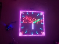
The front & rear view of the clock is shown in several pictures. Look at the final matrix connections on the back. To support the wafer like thin constructions of the individual matrices, we have fixed a few pieces of hard boards with cellophane tapes. Also the individual matrix edges are paste to each other by cellophane tapes as well. You can use plastic glue also for better results.
Schematic:
The 5Volt supply is used for lighting the Neopixels while an LV33 or AM1117 is used to drop 5 volt to 3.3 volt further to run the ESP8266. The capacitors C1 & C2 is used to stabilize the voltages further. The ground connections are common for both the voltages. The 16x16 Matrices ,if you look carefully you would find that it is made of four 8x8 matrices. Therefore, we have symbolized the 4 nos 16x16 matrices by 16 nos 8x8 matrices in our schematic. In the final array connection it is 2x2 [row & column] arrangements.
Operation: After fixing the hardware on a General purpose PCB, switch on the SMPS and check that the 5Volt supply is on. Find a place near the window or the balcony so that the GPS receiver can make connection with the GPS satellites. For my first floor room, it even gets connected while hanging on the wall near the ceiling!
The GPS that I used is GM-22U7 which is extremely fast to get connected with the satellites and the time & date appears within a few seconds on the OLED screen. The use of the OLED 128x64 is optional. I used it just to see what is happening with the GPS signals. You can remove it from the PCB and the clock will still work.
Every minute the color will change. The color scheme is defined in the array matrix colors.h file. The colors.h file has to be in the same folder of the main sketch file.
Software: attached.
16_16_LED_MATRIX1.ino : I have inserted this sketch which will help you to test your matrices with a small graphics display. If your matrices are rightly connected, your will find this small graphics dancing all over the setup.
Bye bye,
Somnath Bera
Vindhyanagar / India
The 16x16 neo pixel was available for just USD 12.5 from aliexpress.com and before I had any idea how to use it or what to build out of it, I just ordered four such matrices. The package arrived just before the country wide lock down started. In the prolong 39 days lock down of first phases, I had the four matrices sat on my table , teasing me all day & night, having just no idea how to use them productively.
That was the time I was working for a breaker open / close indication associated with a danger signal at the local switch gear room and I thought that this 16x16 [256] LEDs can act as a very good alarm signal display – RED or GREEN in one place !
While I rolled up my sleeves and started connecting the panels I got the idea of making everything in one place – Alarm signal display [RED or GREEN] and a huge dial clock when the alarm is not in use besides displaying some graphics as well. First lets see what is required for this.
Bill of Materials & sources:
ESP8266 D1 Mini - 1 no = USD 4.0
16x16 NEO Pixel matrix – 4 nos = USD 50.0 [https://www.aliexpress.com/item/32339610305.html]
High quality quick response GM-22U7 GPS receiver – 1 no = USD 8.8 [https://www.aliexpress.com/item/32813781151.html ]
SSD1306 I2C 64x128 Black & white OLED display [optional] = USD 2.0 [https://www.aliexpress.com/item/32896971385.html ]
5Volt ,6 AMP SMPS – 1 no = USD 9.0 [https://www.aliexpress.com/item/32986101102.html ]
AMS1117 – 3.3 volt regulator = USD 1.0 [https://www.aliexpress.com/item/32890800832.html]
Total = USD 74.8
Since each neopixel takes about 60mA at 5 Volt for 100% brightness, huge current is required to light up 1024 LEDs at full glory! That’s why the bigger the capacity of the SMPS the better it becomes. However, we have set brightness to 40% and considering at a time not more than 20% LEDs will light up at one color [either of Red, Green or Blue :: 1/3].
The power requirements will be = 1024 x 60 x 0.20 x 1/3 = 3684 mA ~ 4 Amp. Therefore, our 6 Amp , 5 Volt SMPS is jolly good for our work.
Time keeper: GPS , Real Time clock or Internet
Since ESP8266 can be joined to WiFi hot spot, the use of GPS receiver is optional for time keeping. It can be supplemented by a suitable RTC DS3231 or NPT server from Internet. However, I’ve an obsession for GPS receivers which obliterates the usage of all other time keeping devices like RTC or others. Once the time is received either from GPS or RTC or NTP server, it is placed on the 4 matrices with lots of bonanzas of colors & drawings!
Prototype:
The front & rear view of the clock is shown in several pictures. Look at the final matrix connections on the back. To support the wafer like thin constructions of the individual matrices, we have fixed a few pieces of hard boards with cellophane tapes. Also the individual matrix edges are paste to each other by cellophane tapes as well. You can use plastic glue also for better results.
Schematic:
The 5Volt supply is used for lighting the Neopixels while an LV33 or AM1117 is used to drop 5 volt to 3.3 volt further to run the ESP8266. The capacitors C1 & C2 is used to stabilize the voltages further. The ground connections are common for both the voltages. The 16x16 Matrices ,if you look carefully you would find that it is made of four 8x8 matrices. Therefore, we have symbolized the 4 nos 16x16 matrices by 16 nos 8x8 matrices in our schematic. In the final array connection it is 2x2 [row & column] arrangements.
Operation: After fixing the hardware on a General purpose PCB, switch on the SMPS and check that the 5Volt supply is on. Find a place near the window or the balcony so that the GPS receiver can make connection with the GPS satellites. For my first floor room, it even gets connected while hanging on the wall near the ceiling!
The GPS that I used is GM-22U7 which is extremely fast to get connected with the satellites and the time & date appears within a few seconds on the OLED screen. The use of the OLED 128x64 is optional. I used it just to see what is happening with the GPS signals. You can remove it from the PCB and the clock will still work.
Every minute the color will change. The color scheme is defined in the array matrix colors.h file. The colors.h file has to be in the same folder of the main sketch file.
Software: attached.
16_16_LED_MATRIX1.ino : I have inserted this sketch which will help you to test your matrices with a small graphics display. If your matrices are rightly connected, your will find this small graphics dancing all over the setup.
Bye bye,
Somnath Bera
Vindhyanagar / India
Discussion (3 comments)