Interested in audio-related projects? One of the most popular Elektor projects in 2015 was Burkhard Kainka's medium-wave AM transmitter design. Let’s revisit the creative Arduino Uno-based design.
Interested in audio-related projects? One of the most popular Elektor projects in 2015 was Burkhard Kainka's medium-wave AM transmitter design. Let’s revisit the creative Arduino Uno-based design.
The Arduino-powered AM transmitter was fairly straightforward. As Kainka explained, a transmitting tube was driven hard by the carrier signal (Class C final stage), with its anode voltage modulated by the audio signal. "For flea power, we can do the same thing with a transistor, either bipolar or FET," he explained. "All we need then is a crystal-controlled RF signal on the appropriate frequency."
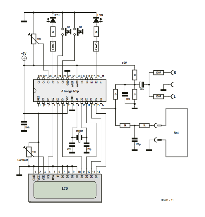
AM Transmitter Circuit
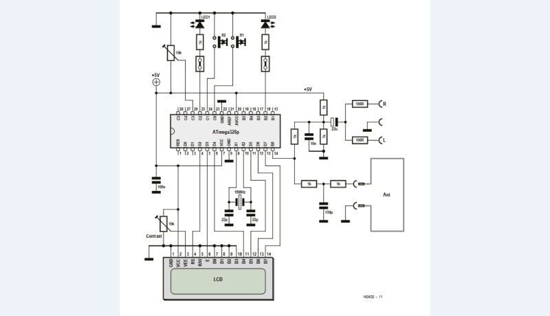
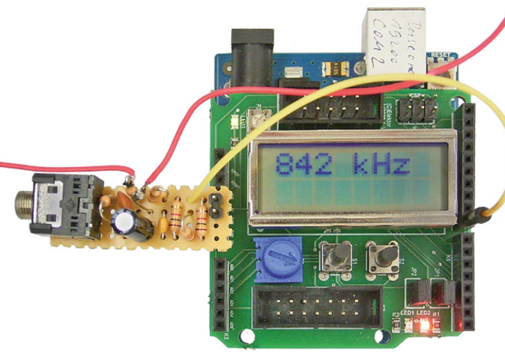
Refer to the AM transmitter circuit. All components on the left-hand side are located on the Arduino Uno and the Elektor Extension Shield.
All components on the left-hand side are located on the Arduino Uno and the Elektor Extension Shield.
A few of resistors and capacitors “condition” the audio signal. The left-hand side of the schematic includes the Arduino Uno’s ATmega328 and the components located on the Extension Shield. At the antenna output is a simple low-pass filter for suppressing the harmonics.
“Theoretical considerations and actual measurements both indicate somewhat less than 0.3 mA of current should flow in the loop antenna,” Kainka explained. “You will be well within the guidelines so long as the total length of wire in the loop antenna is not greater than 3 meters. For your first tests a far smaller wire loop will be fine (using just 20 cm of wire for example).”
The AM transmitter design
The Original Project
The article, “Arduino-Powered AM Transmitter” appeared in Elektor May/June 2015. You can download this article for free during the two weeks following the publication of this news item. Enjoy the article!
Editor's Note: This article was first published in a 2015 edition of ElektorMag. Some of the components, products, and links may no longer be available. Still, the educational content remains valuable, and we think it will inspire you at your workbench.
Subscribe
Tag alert: Subscribe to the tag Circuits & Circuit Design and you will receive an e-mail as soon as a new item about it is published on our website!





Discussion (3 comments)