Many radio enthusiasts employ two types of receivers, one portable and one fixed. This DSP radio is versatile, functioning as either type thanks to its USB interface, which also allows for computer control. Check out the circuit.
In practice, many radio enthusiasts employ two types of receivers: a portable one and a fixed receiver that can be controlled via a computer. Elektor’s DSP radio is versatile, functioning as either type thanks to its USB interface, which also allows for computer control. This USB interface not only facilitates PC control but also powers the receiver, with the audio output linking to the PC’s powered speakers. For mobile use, the design includes an audio amplifier compatible with a 6-V battery, supporting one or two loudspeakers for enhanced portability and convenience. Let's take a closer look at the DSP radio circuit.
The Receiver Circuit
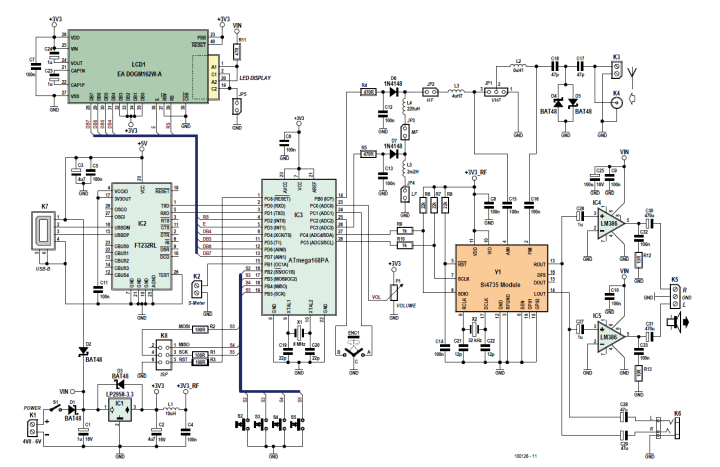
At first glance, the circuit of the receiver does not look much like a traditional RF design. All the important functions are integrated in an Si4735. Only the antenna connection points to the RF nature of the circuit.
The only hint that this is the circuit diagram of a radio receiver is the antenna input circuitry.
The designer, Burkhard Kainka, explains:
"The antenna signal arrives at BNC socket K4 or at screw terminals K3 and passes through a diode limiter comprising D4 and D5. L2 is an FM coil with an inductance of 0.1 μH. In normal operation jumper JP1 is set to bridge pins 2 and 3, which connects the end of the FM coil to the AM input. What is not visible from the circuit diagram is that in FM mode the receiver sets its internal AM ‘variable capacitor’ to 500 pF, which, as far as RF is concerned, shorts the end of the FM coil to ground. In AM mode, however, the signal from the antenna passes via L2, which now acts to increase the effective antenna length, to the AM resonant circuit comprising L3, L4, L5 and the automatically tuned ‘variable capacitor’ inside the Si4735 at pin 4 (AMI). Which of the fixed inductances is actually used is determined by IC3 using the switching circuit comprising 1N4148 diodes D6 and D7, which can effectively short a selected part of the inductance in the circuit to ground. In normal use jumpers JP2, JP3 and JP4 are closed; opening these jumpers allows the connection of alternative antenna input circuits or of a ferrite antenna. For example, a mediumwave ferrite antenna can be connected at JP3 or a shortwave loop antenna at JP2. If a whip antenna is to be used for FM reception only, set JP1 to bridge pins 1 and 2.”
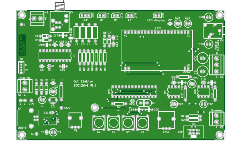
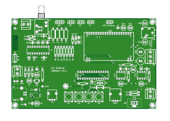
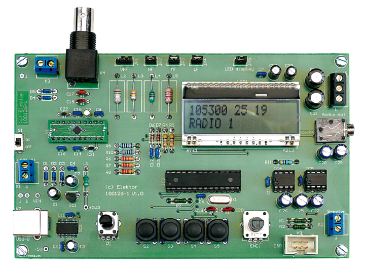
The PCB. All user controls are mounted on the top side of the board for convenience.
All the controls are located on the top surface of the board. The Si4735 module consists of a daughter board with the DSP IC mounted on it.
The main functions are handled with an Si4735 DSP radio IC with the help of an LCD-based UI,
a stereo audio amp, and an interface that allows the receiver to be controlled from a PC.
Elektor Magazine has been one of the leading sources of information on electronics for engineers, designers, start-ups and companies for 65 years. Our magazine is powered by an active community of electronics engineers – from students to professionals – who are passionate about designing and sharing innovative ideas.
For them, we publish hundreds of items a year, in formats such as articles, videos, webinars, and other learning formats. Our mission is to share knowledge in every possible way and inspire readers with the latest developments within the electrical engineering sector.
Thank you for your vote!
Leave further comments in the fields below.
Thank you for your vote!
If you wish to leave a comment with your rating, please first use the login below. If not, just close this window.


Discussion (0 comments)