Want to design a battery level indicator? Would you like to construct a magnetic levitation device? Curious about what Elektor was predicting for USB technology 20 years ago? This month, we highlight interesting articles and projects from past Septembers. Get inspired!
Want to design a battery level indicator? Would you like to construct a magnetic levitation device? Curious about what Elektor was predicting for USB technology over 20 years ago? As part of our Elektor 60 celebration, we are regularly spotlighting at stand-out electronics articles, DIY projects, and engineering tutorials from the past. Check out the following articles from previous September editions of Elektor. We found them inspiring. Let us know what you think.
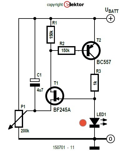
Low-Battery Indicator for 9 V Batteries (2016)
You are likely familiar with Elektor's famous, in-depth design projects, like the Junior Computer (1980), ElektorWheelie (2009), and the LCR Meter: 50 Hz- 2 MHz (2020). But many smaller projects have been crowd pleasers as well. For instance, this project features a retro-fitted the amplifier circuit with a low-battery indicator. Need a great solution for monitoring a 9-V battery? You can build something similar without an microcontroller or an op-amp.
DIY low battery indicator
"The red LED has a dual function in this circuit," Dr. Rainer Giedigkeit explains. "Not only does it act as an indicator to let you know that the battery voltage is low but the forward voltage drop across the LED is used as a reference voltage level."
It's a nice engineering solution. You don't need to guess the battery's state of charge!
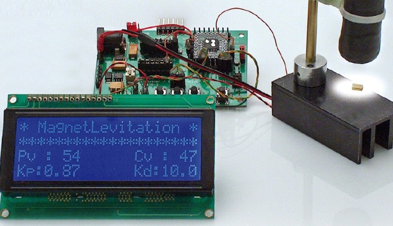
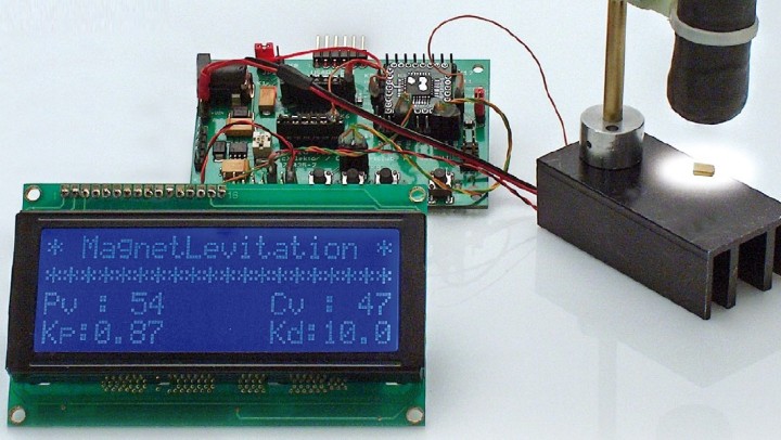
Light as Air: Using the ATM18 to Control a Magnet Levitation Device (2008)
You've likely read our recent articles about magnetic levitation. But did you know we've been publishing projects on the topics for several years. In September 2008, Udo Jürß and Wolfgang Rudolph presented an interesting design that used a Hall sensor, rather than a light barrier, to detect the position of the levitated object.
Use an ATM18 to control a magnet levitation device.
"With the usual levitation devices, which have already been described in DIY articles in past issues of Elektor, the beam of a light barrier is more or less obstructed by the ‘floating’ object," they explained. "The amount of light received by the sensor of the light barrier is used to control the amount of current flowing through the coil. The mechanical and electronic construction of the device is designed to maintain the levitated metal object in the prescribed position. Distance control using a Hall sensor is based on a completely different principle."
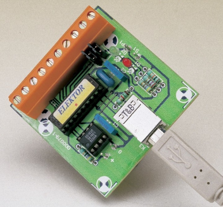
USB Interface: Experimenting with the Universal Serial Bus (2000)
Elektor community members were experimenting with USB more than 20 years ago. As B. Kainka explained, "In the long term, this new serial interface could replace many of the PC interfaces that have been used up to now. This is reason enough for looking at it more closely." He was right! The USB Interface presented in the article is based on a Cypress application. A USB thermometer was available in the CY3640 starter kit. The author resurrected it in this Elektor project.
USB interface
"Once everything has been assembled and there are no obvious construction errors, there comes the moment of truth," Kainka wrote. "Connect the USB Interface to a PC using a type A–B USB cable. After a moment, Windows will recognise that new hardware has been connected."
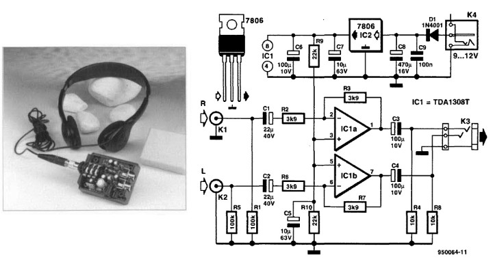
Headphone Amplifier (1995)
Back in September of 1995, Ton Giesberts pointed out that, on a lot of audio equipment, "the headphone output is simply derived from the loudspeaker output via a series resistor: not a very elegant design!" So what did he do? In typical Elektor fashion, he set out to design a solution. "The present circuit describes a 'real' headphone amplifier that can be added to most equipment, but may also be used as a stand-alone unit."
Circuit diagram of the headphone amplifier.
A little soldering is needed, but as Giesberts explained, a little patiences and fine soldering tip will do the job. The various connectors are soldered directly to the board: two phono plugs for inputs K1 and K2; an adaptor socket for K4 and a 6.3-mm stereo jack for K3. These connectors are, of course, required only if the amplifier is to be used as a standalone unit, Giesberts explained.
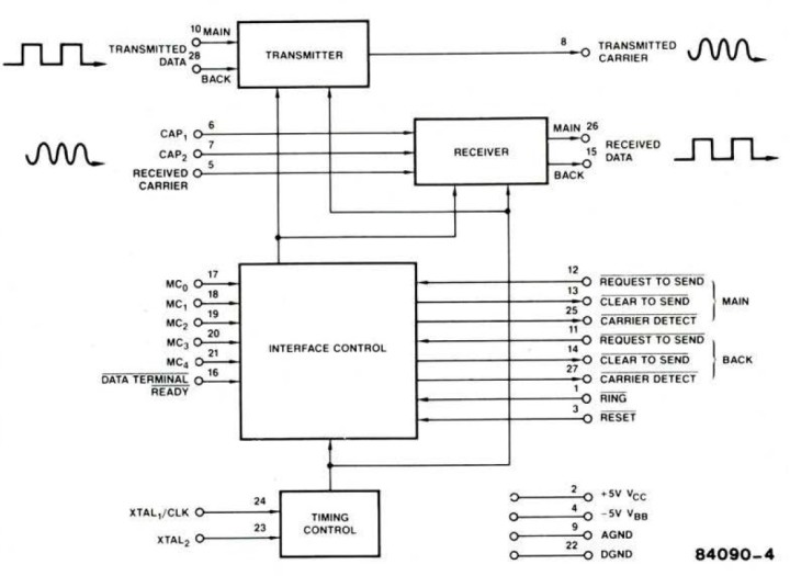
Data Transmission by Telephone (1984)
There was a time when the idea of two computers "conversing" sounded more like science fiction than reality. In September 1984, Elektor asked the question: How do two computer converse over the telephone lines?
"The connection between computer (or terminal) and telephone line is made via a so-called modem (MOdulator/DEModulator)," Elektor wrote. "Two basic types of modems exist: acoustically-coupled and direct-coupled. In the case of the first of these the information must be exchanged with the telephone handset via a microphone and a loudspeaker. The second type, as its name suggests, is connected directly to the telephone line."
In the AM 7910 IC, a complete modem is fitted onto a single chip. The signals are processed completely digitally.
The article offers you more than a trip down memory lane. It covers essential technical topics such as modem technology, carrier waves, and different methods of modulation.
More Engineering to Come
These are just a few of the thousands of classic Elektor electronics projects and engineering tutorials our members can enjoy. Next time, we'll highlight a few of the editorial team's favorite articles from past Octobers. The engineering never stops. Take out an Elektor membership to start enjoying the entire Elektor library.
Elektor Magazine has been one of the leading sources of information on electronics for engineers, designers, start-ups and companies for 65 years. Our magazine is powered by an active community of electronics engineers – from students to professionals – who are passionate about designing and sharing innovative ideas.
For them, we publish hundreds of items a year, in formats such as articles, videos, webinars, and other learning formats. Our mission is to share knowledge in every possible way and inspire readers with the latest developments within the electrical engineering sector.
Thank you for your vote!
Leave further comments in the fields below.
Thank you for your vote!
If you wish to leave a comment with your rating, please first use the login below. If not, just close this window.

Discussion (0 comments)