
Engineering in September: Wireless from the Workbench
September 21, 2022
on
on
The Elektor library is packed with amazing wireless-realted projects and engineering tutorials. Here we look back at several memorable wireless articles from past September editions of your favorite magazine.
If you follow Ilse’s advice, you can build a similar project in about 2 hours for less than €75.
"The most important prerequisite for this redesign was the freedom to re-use the sensor and existing assembled PCB without needing any modification to the software in the Microchip PIC16F876 controller," he explained. "Sensor and controller alike should be unaware of (and unaffected by) the modification."
"It is expected that the incorporation of the LED-based tuning system enables users to get stable reception of teletype messages fairly quickly," the author explains. "The maximum baud rate the interface can handle is about 100 baud, although 200 baud has been achieved when receiving a strong and interference-free signal, which, unfortunately, is something of a rarity on the SW bands nowadays."
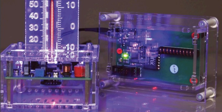
A Wireless Temperature Sensor for the Nixie Bargraph Thermometer (September 2020)
In 2020, we published an interesting article by Ilse Joostens about how she turned a Nixie bargraph thermometer into a wireless device. The transmitter circuit features a Microchip Technology ATmega328P-AU microcontroller ticking at 8 MHz using a crystal for its oscillator. Based on the same MCU, the receiver shares an antenna with the transmitter.If you follow Ilse’s advice, you can build a similar project in about 2 hours for less than €75.
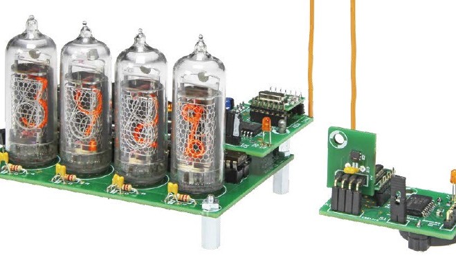
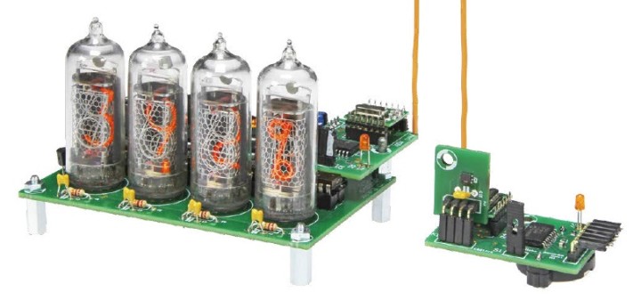
Wireless I2C Sensor (September 2015)
A nixie tube thermometer/hygrometer featured in the June 2012 edition of Elektor Mag combined old-school components with a modern microcontroller. A few years after that project was published, Hans Oppermann upgraded the design with two wireless modules to connect the sensor and temperature display."The most important prerequisite for this redesign was the freedom to re-use the sensor and existing assembled PCB without needing any modification to the software in the Microchip PIC16F876 controller," he explained. "Sensor and controller alike should be unaware of (and unaffected by) the modification."
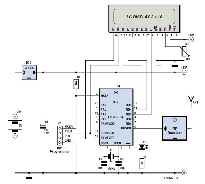
Watchdog in the Meter Cabinet: Wireless Energy Monitor (September 2007)
Energy consumption applications are all the rage in 2022. But there were far fewer innovative options on the market back in 2007. Fortunately, innovative Elektor community engineering aficionados were developing solutions of their own. Jeroen Peters's Wireless Energy Monitor is an excellent example. The meter consists of several sensors with a transmitter and a receiver. "The transmitter and the sensors are placed in the meter cabinet next to the electricity meter and gas meter," he noted. "You can use the doorbell transformer to power the transmitter. Thanks to the wireless link, the receiver can be used anywhere in the house to show your current power consumption on a LCD screen. You can thus use it in every room to see the effect on energy consumption of switching something on or off. The receiver is powered by a 9-V battery."418/433 MHz Control System (September 1998)
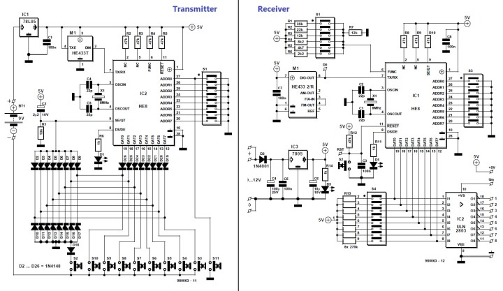
The 433/418 MHz wireless control system covered in this September 1998 article offers high-quality technology for a large number of applications, with special emphasis on reliability, security, and connectivity. The transmitter consists basically of a 433-MHz SRD transmitter module and a special encoder IC. The receiver employs the same data encoder/decoder IC as the transmitter. The behavior of the eight outputs is determined by six different modes selected by DIP switches in array S1.RTTY Interface (September 1986)
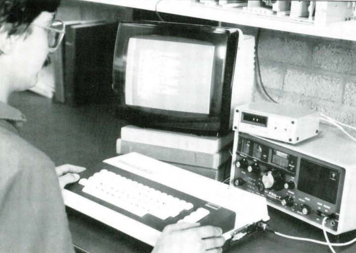
Back in 1986, Elektor covered the topic of radio teletype (RTTY) signals. In conjunction with an RTTY software package, the interface described in the article, “RTTY Interface,” enables the received teletype message to be displayed on a computer monitor."It is expected that the incorporation of the LED-based tuning system enables users to get stable reception of teletype messages fairly quickly," the author explains. "The maximum baud rate the interface can handle is about 100 baud, although 200 baud has been achieved when receiving a strong and interference-free signal, which, unfortunately, is something of a rarity on the SW bands nowadays."
The Engineering Never Stops
In October, we will remind of you of more classic Elektor articles, projects, and tutorials. If you have any ideas or feedback, please share your thoughts in the comments section below. Keep the engineering going!Read full article
Hide full article
Discussion (0 comments)