
ESP32/STM32 Power Supply System
When you need to power any microcontroller such as the ESP32 and the STM32, you do not plug it directly into the wall power outlets. The power coming out of the wall is too much for the microcontroller. Therefore, you need to design a power supply system that is capable to help you achieve the goal of powering these microcontrollers. We shall be doing one such power system in this project.
In this project, am going to design an ESP32/STM32 power supply system. From the research, I have taken note that the ESP32 and the STM32 are powered by a 3V3 output power supply system. For this project, our input will be a 5V input which will be through a USB port.
Components
1. USB port – 5V
2. capacitor- 68uF SMD and electrolytic
3. Capacitor – 120 uF
4. IC- LM2594M- 3V3------------Voltage regulator which takes an input up to 60 VDC
5. Diode- Schottky type of diode
6. Inductor- 100 uH
7. Connector_01x02; Terminal block
Schematic:
Here, the schematic main part is the LM2594M-3.3 voltage regulator which regulates the input voltage by stepping it down from 5V to 3V3 volts which is necessary for powering our ESP32/STM32. The voltage regulator will receive the 5V from the USB port then regulate it and pass it to the terminal block which will be an output of 3.3V at 500mA of power.
PCB Layout:
The PCB layout is carried out and here all the routing process takes place to ensure that all the components and the ground are connected by drawing the copper traces.
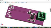
3D view
Here we generate the actual view of how the final PCB outlook will appear. This is the point where you even set the colors of your PCB to the required colors.
Generation of the manufacturing files;
1. Gerber files
2. Pick and place files
3. Drill files
4. BOM files
Build This Project
Bring this design to life with the Elektor PCB Service, powered by Eurocircuits. Upload the project files and order professionally manufactured PCBs or assembled boards through a proven European production platform.
Supporting KiCad, Eagle, Gerber, and ODB++ formats, the service is suitable for everything from prototypes and validation builds to series production and volume manufacturing.
Made in Europe. Fast. Reliable. Professional.
Discussion (3 comments)