
Flux-gate compass
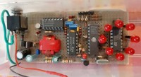
This is a fully functional flux-gate compass made at home from scratch. A physics demonstrator that could be useful sometimes, but also a source of great design gratification!
This project consists of a flux-gate magnetic compass built from scratch. The flux-gate is one of the several techniques that allow to measure constant magnetic fields (for the variable ones the laws of magnetic induction are usually sufficient), which I find particularly interesting from a physical and implementation point of view.
It's an old design: I made it in 1995 and still works. According to me, the principle is still interesting, and the project could still be reproduced as is, using an ST62E10 microcontroller that, however, may be hard to find. The project could also be adapted to a more modern micro: for example, an Arduino Nano, or simply its microcontroller, would be much more powerful than the original one and would allow to easily code the program in C/C++.
You can find project details, including the microcontroller source and executable code, in the repository https://github.com/rvisent/Flux-gate_compass.
Photos are here: https://github.com/rvisent/Flux-gate_compass/tree/main/photos
Here is a short video: https://youtube.com/shorts/MnPGs99Pc7o
The project was proposed for publication in an italian magazine of the time, but wasn't actually published.
Characteristics
The device allows the measurement of weak magnetic fields such as the terrestrial one (and up to about 10 times more intense), with direct display of the North direction on LEDs. Direction and intensity of the field can be read by interfacing with the parallel port of a PC: in this configuration the device is not just a compass, but a magnetometer. The LEDs used for direct display for simplicity are only 8 arranged in a circle, but with a resolution equivalent to 32 (about 12 degrees), because the indication is provided by two contiguous LEDs with continuous modulation of the light intensity. The interface with the PC allows a higher resolution but, at least with the sensor (toroidal core) used in this prototype, too much precision is not to be expected: at most a few degrees, which, however, I consider a more than sufficient result for a hobby realization.
Working principle
As already mentioned, the sensor used is a flux-gate, a device that allows the measurement of a static magnetic field such as the terrestrial one using an artifice to transform it into a variable field; once made variable, this can excite a solenoid (actually two, orthogonally arranged to detect the direction and intensity of the field on a plane), which produces an e.m.f. directly proportional to the intensity of the original field and to the speed of the variation imposed. The trick adopted consists in the use of a toroidal core with high magnetic permeability, periodically saturated by feeding a suitable signal on the main winding arranged along the core (i.e. in the conventional way): when the core saturates, its permeability is reduced to little more than that of vacuum. Seen from the outside, the core behaves like a variable permeability piece of ferrite, because the exciting field is well shielded by the toroidal core, which has a very low flux dispersion (if properly wound!). Therefore, two windings arranged orthogonally to each other above the core, as in figure 1, are able to read the above mentioned e.m.f.
In practice, the measured signal contains a component of the exciting field which acts as a disturbance, so it is not sufficient to measure the amplitude of the induced signal, but a synchronous sampling followed by low-pass filtering is necessary. In our case, the excitation signal is a square wave (in voltage) having about 700 Hz frequency and a peak-to-peak amplitude of 7-9 V. The current has a triangular shape with high cusps corresponding to the edges of the square wave, due to saturation and de-saturation of the core. The peak current is about 200 mA, compared to an RMS value of a few mA; such a strong saturation is necessary to adequately lower the permeability of the core. The synchronous sampling is performed only on the de-saturation cycle, for a time of 40 µs: this for simplicity, since the useful signal related to de-saturation begins exactly at the inversion of the exciting field, while the position of the one related to saturation depends on the amplitude of the excitation (see figure 2). Furthermore, the two signals are of opposite sign, so using both of them would require a greater number of components...
The core used was recovered from the common-mode mains filter of a PC switching power supply. From the dimensions (14x9x5 mm), from the orange color and from the measured characteristics I believe it is the Philips 37110 model in ferrite 3E25 or an equivalent component. However, it would certainly be worthwhile to evaluate samples of different types, as long as they are in ferrite (easy to saturate) and with high permeability. Keep in mind that, with the same permeability, a larger core would improve the quality of the measurements, but would require a higher driving current. The number of turns of the excitation winding (about 300) has been thought to work between 9 and 12 V with an excitation frequency of 700-1000 Hz. The measurement windings, on the other hand, were made without thinking too much (50 turns each), and I think we could at least double the number of turns for the benefit of the rest of the circuit.
The ST62E10 microcontroller performs most of the circuit functions. In fact, it:
The power driver consists of a pair of small power mosfets (rdson = 5 ohms). I have previously experimented with a driver based on a pair of BC327 / BC337 transistors, with more or less the same results. Other mosfets are certainly usable, paying attention to the driver circuit in case of high gate capacitance, to avoid excessive dissipation during switching due to the CMOS-style connection.
The signal conditioning circuit consists, for each channel, of an analog switch (s1-s3) and a lossy integrator (i.e. a very low-pass amplifier). A second switch (s2-s4) allows to sample the voltage Vref, thus measuring the contribution of offset and bias of the op-amps that implement the integrators. The output signal in the direction of maximum of the earth's magnetic field is about 300 mV (with respect to the voltage measured in calibration). It could be argued that this is a bit too small to allow for precise measurements with 8-bit sampling with 5 V f.s. of the ST6: it is true, but I think it would be enough to double the number of turns of the windings Ls1, Ls2 to reach a more than sufficient precision (however, I have not tried). I don't think it would be worthwhile to increase the gain (already very high) of the integrator: this would require the addition of an amplifier stage. I also do not think it would be convenient to increase the signal amplitude too much, because you would lose the possibility of measuring fields that are more intense than the terrestrial one (e.g. a magnet). Unless you want to provide two or more measurement ranges...
The reference voltage is 2.5 V, supplied by a simple resistive divider starting from the 5 V that power the ST6. It is not critical thanks to the self-calibration.
The Lp peak current meter is a simple half-wave rectifier. It takes advantage of the LM324's ability to work with the inputs at the same potential or even slightly below the negative power supply bar. The stage is not critical at all. The voltage produced at the output is about 3.5 V, with a considerable ripple superimposed due to the jitter in the signal driving Lp. This jitter (some µs) is due to the processor interrupt response time and is unfortunately inevitable: however it does not cause particular problems.
The driving of the LEDs is carried out in multiplex by means of a 74HC138, used with an unusually high output current of about 18 mA (however far from the absolute maximum rating of 25 mA). A single resistor limits the current for all the LEDs, as there is always one and only one LED lit, despite the appearance.
The interface with the PC is made through 3 lines of the parallel port of this, and is of the synchronous serial type: the PC sends a clock signal, to which the ST6 responds with a data bit and an acknowledge signal. The total packet transferred is of 24 bits, comprising 18 data bits (9 per channel) plus 3 identification and 3 checksum bits. An RS-232 serial interface was not chosen due to the extreme difficulty of implementation on the ST6, being the only existing timer already engaged at high speed. The hardware connection with the PC was made with 3 resistors in order to protect the ST6 without complicating the circuit too much: in a final version, it would probably be better to use buffers (e.g. 74HC14), but there was not enough room in the prototype board...
The total absorption is about 30 mA (of which 18 for the LEDs), good for occasional (not continuous) use with a 9 V alkaline battery.
It's an old design: I made it in 1995 and still works. According to me, the principle is still interesting, and the project could still be reproduced as is, using an ST62E10 microcontroller that, however, may be hard to find. The project could also be adapted to a more modern micro: for example, an Arduino Nano, or simply its microcontroller, would be much more powerful than the original one and would allow to easily code the program in C/C++.
You can find project details, including the microcontroller source and executable code, in the repository https://github.com/rvisent/Flux-gate_compass.
Photos are here: https://github.com/rvisent/Flux-gate_compass/tree/main/photos
Here is a short video: https://youtube.com/shorts/MnPGs99Pc7o
The project was proposed for publication in an italian magazine of the time, but wasn't actually published.
Characteristics
The device allows the measurement of weak magnetic fields such as the terrestrial one (and up to about 10 times more intense), with direct display of the North direction on LEDs. Direction and intensity of the field can be read by interfacing with the parallel port of a PC: in this configuration the device is not just a compass, but a magnetometer. The LEDs used for direct display for simplicity are only 8 arranged in a circle, but with a resolution equivalent to 32 (about 12 degrees), because the indication is provided by two contiguous LEDs with continuous modulation of the light intensity. The interface with the PC allows a higher resolution but, at least with the sensor (toroidal core) used in this prototype, too much precision is not to be expected: at most a few degrees, which, however, I consider a more than sufficient result for a hobby realization.
Working principle
As already mentioned, the sensor used is a flux-gate, a device that allows the measurement of a static magnetic field such as the terrestrial one using an artifice to transform it into a variable field; once made variable, this can excite a solenoid (actually two, orthogonally arranged to detect the direction and intensity of the field on a plane), which produces an e.m.f. directly proportional to the intensity of the original field and to the speed of the variation imposed. The trick adopted consists in the use of a toroidal core with high magnetic permeability, periodically saturated by feeding a suitable signal on the main winding arranged along the core (i.e. in the conventional way): when the core saturates, its permeability is reduced to little more than that of vacuum. Seen from the outside, the core behaves like a variable permeability piece of ferrite, because the exciting field is well shielded by the toroidal core, which has a very low flux dispersion (if properly wound!). Therefore, two windings arranged orthogonally to each other above the core, as in figure 1, are able to read the above mentioned e.m.f.
see picture figure 1
In practice, the measured signal contains a component of the exciting field which acts as a disturbance, so it is not sufficient to measure the amplitude of the induced signal, but a synchronous sampling followed by low-pass filtering is necessary. In our case, the excitation signal is a square wave (in voltage) having about 700 Hz frequency and a peak-to-peak amplitude of 7-9 V. The current has a triangular shape with high cusps corresponding to the edges of the square wave, due to saturation and de-saturation of the core. The peak current is about 200 mA, compared to an RMS value of a few mA; such a strong saturation is necessary to adequately lower the permeability of the core. The synchronous sampling is performed only on the de-saturation cycle, for a time of 40 µs: this for simplicity, since the useful signal related to de-saturation begins exactly at the inversion of the exciting field, while the position of the one related to saturation depends on the amplitude of the excitation (see figure 2). Furthermore, the two signals are of opposite sign, so using both of them would require a greater number of components...
see picture figure 2
The core used was recovered from the common-mode mains filter of a PC switching power supply. From the dimensions (14x9x5 mm), from the orange color and from the measured characteristics I believe it is the Philips 37110 model in ferrite 3E25 or an equivalent component. However, it would certainly be worthwhile to evaluate samples of different types, as long as they are in ferrite (easy to saturate) and with high permeability. Keep in mind that, with the same permeability, a larger core would improve the quality of the measurements, but would require a higher driving current. The number of turns of the excitation winding (about 300) has been thought to work between 9 and 12 V with an excitation frequency of 700-1000 Hz. The measurement windings, on the other hand, were made without thinking too much (50 turns each), and I think we could at least double the number of turns for the benefit of the rest of the circuit.
The prototype schematic is shown in figure 3.
The ST62E10 microcontroller performs most of the circuit functions. In fact, it:
- generates the square wave necessary to drive the excitation coil Lp;
- generates the 40 µs pulse necessary for synchronous sampling, with which it controls switches s1 and s3 (or s2 and s4, see below);
- acquires the intensity signals of the two components of the field;
- calculates the direction of the field and drives the LEDs with brightness modulation to increase the resolution;
- manages communications with the PC, to which it supplies the two measured components;
- provides for the adaptation of the working frequency to stabilize the peak current on the coil Lp at the required value of 200 mA when the supply voltage varies;
- performs an initial self-calibration of the circuit, to compensate the offset voltage and bias current of the opamps that condition the measured signal. This function is achieved by closing switches s2-s4 in place of s1-s3 for about one second after switching on (the time to bring both the operating frequency and the integrators to steady state by means of the current control). The voltage values measured on the two channels at the end of the self-calibration are subsequently subtracted from the measurements. The circuit is able to function correctly even in the worst cases of offset and bias reported in the LM324 data sheet.
The power driver consists of a pair of small power mosfets (rdson = 5 ohms). I have previously experimented with a driver based on a pair of BC327 / BC337 transistors, with more or less the same results. Other mosfets are certainly usable, paying attention to the driver circuit in case of high gate capacitance, to avoid excessive dissipation during switching due to the CMOS-style connection.
The signal conditioning circuit consists, for each channel, of an analog switch (s1-s3) and a lossy integrator (i.e. a very low-pass amplifier). A second switch (s2-s4) allows to sample the voltage Vref, thus measuring the contribution of offset and bias of the op-amps that implement the integrators. The output signal in the direction of maximum of the earth's magnetic field is about 300 mV (with respect to the voltage measured in calibration). It could be argued that this is a bit too small to allow for precise measurements with 8-bit sampling with 5 V f.s. of the ST6: it is true, but I think it would be enough to double the number of turns of the windings Ls1, Ls2 to reach a more than sufficient precision (however, I have not tried). I don't think it would be worthwhile to increase the gain (already very high) of the integrator: this would require the addition of an amplifier stage. I also do not think it would be convenient to increase the signal amplitude too much, because you would lose the possibility of measuring fields that are more intense than the terrestrial one (e.g. a magnet). Unless you want to provide two or more measurement ranges...
The reference voltage is 2.5 V, supplied by a simple resistive divider starting from the 5 V that power the ST6. It is not critical thanks to the self-calibration.
The Lp peak current meter is a simple half-wave rectifier. It takes advantage of the LM324's ability to work with the inputs at the same potential or even slightly below the negative power supply bar. The stage is not critical at all. The voltage produced at the output is about 3.5 V, with a considerable ripple superimposed due to the jitter in the signal driving Lp. This jitter (some µs) is due to the processor interrupt response time and is unfortunately inevitable: however it does not cause particular problems.
The driving of the LEDs is carried out in multiplex by means of a 74HC138, used with an unusually high output current of about 18 mA (however far from the absolute maximum rating of 25 mA). A single resistor limits the current for all the LEDs, as there is always one and only one LED lit, despite the appearance.
The interface with the PC is made through 3 lines of the parallel port of this, and is of the synchronous serial type: the PC sends a clock signal, to which the ST6 responds with a data bit and an acknowledge signal. The total packet transferred is of 24 bits, comprising 18 data bits (9 per channel) plus 3 identification and 3 checksum bits. An RS-232 serial interface was not chosen due to the extreme difficulty of implementation on the ST6, being the only existing timer already engaged at high speed. The hardware connection with the PC was made with 3 resistors in order to protect the ST6 without complicating the circuit too much: in a final version, it would probably be better to use buffers (e.g. 74HC14), but there was not enough room in the prototype board...
The total absorption is about 30 mA (of which 18 for the LEDs), good for occasional (not continuous) use with a 9 V alkaline battery.
Build This Project
Bring this design to life with the Elektor PCB Service, powered by Eurocircuits. Upload the project files and order professionally manufactured PCBs or assembled boards through a proven European production platform.
Supporting KiCad, Eagle, Gerber, and ODB++ formats, the service is suitable for everything from prototypes and validation builds to series production and volume manufacturing.
Made in Europe. Fast. Reliable. Professional.
Discussion (3 comments)