
Functional Safety and its Application to Automated Industrial Cobots
As illustrated in figure 1 there are three main stages to a safety control system – input, logic and output.
A wide range of input devices can be used for control systems including opto-electronic sensors such as light curtains or scanners (Figure 2). These are capable of detecting the physical distance between a human operator and the robot’s area of operation, providing an output signal when safety conditions are breached. Torque or force sensors attached to the robot’s joints or actuator can also be used to detect when resistance to the robot’s movement exceeds a certain force, (e.g. when in contact with an operator).
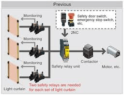
Figure 2: Example safety control circuit using light curtains
(Source: http://www.isac.com.tr/panasonic/urundetay.php?id=325)
The logic function of the control system reacts to the conditions indicated by the input device and generates an output based on the logic programmed into it. This functionality can be performed by a range of devices, from relays to programmable logic controllers (PLCs), such as the modular and configurable PNOZmulti range of controllers from PILZ (Figure 3). These devices are software programmable and have a PL rating of e (SIL of 3) making them suitable for inclusion in robot safety control systems.
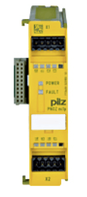
Figure 3: PILZ PNOZ Safety Controller
(Source: https://www.distrelec.de/Web/Downloads/_t/ds/773400_eng_tds.pdf)
Output devices in a safety control system include contactors, motor starters, valves, and other devices that can control motors and other equipment that effects motion in the system in some manner. Omron’s G9SA Safety Relay Series (Figure 4) are designed specifically for safety applications and come with a PL rating of e (SIL 3), making them suitable for use in safety-stop applications.
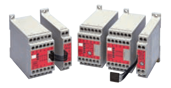
Figure 4: Omron’s G9SA Safety Relay Series
(Source: https://www.distrelec.de/Web/Downloads/_t/ds/G9SA_eng_tds.pdf)
Discussion (0 comments)