
Getting Started with the ESP32-C3 RISC-V MCU
on
The ESP32-C3 from Espressif has been eagerly awaited. It has just one core humming away at its heart instead of the usual two cores in ESP32-based controllers. This core, however, uses the free and open RISC-V instruction set architecture which competes with ARM-based controllers widely used for IoT applications. I recently took a look at the ESP32-C3 and the ESP32-C3-DevKitC-02 to see how it performed in the lab. Let’s review what I learned.
Anyone following the me on Twitter (@ElektorMathias) might have noticed a couple of ESP32-C3 DevKits sitting on my desk. Followers of our Lab Notes in June will also be aware that software support for the ESP32-C3 is still a work in progress. The development kit under the spotlight in this review is fitted with the revision 2 version of the ESP32-C3 chip. These preliminary versions come with an A4 errata sheet (printed on both sides) listing the problems which have so far been identified.
Amongst other things, the revision 2 suffers from insomnia — that is, it draws a high level of power in deep sleep mode, and the USB/JTAG serial adapter in the chip doesn’t function. The more recent revision 3 version should have these problems resolved, as I noted on Twitter.
The Espressif ESP-IDF repository supporting the ESP32-C3 is also a work in progress and may contain bugs. Since Arduino support is based on it, any bugs will migrate onto this platform too. At the time I am writing this article, the Development Release of the Arduino Support Package will need to be installed in the Arduino IDE you are running. To do this, enter the following link under Preference in the Additional Boards Manager URLs:
https://raw.githubusercontent.com/espressif/arduino-esp32/gh-pages/package_esp32_dev_index.json. Which installs the 2.0.0-rc1 version.
Purchasers of dev kits based on the ESP32-C3 should be supplied with the latest rev.3 version of the chip, as can be read in the forum entry at ESP32.com. The preliminary rev.2 buggy version was only fitted to a limited numbers of the first dev kits supplied.
The ESP32-C3 DevKitC-02
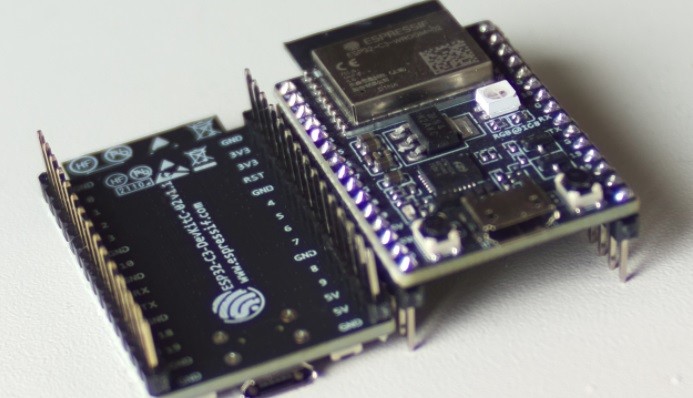
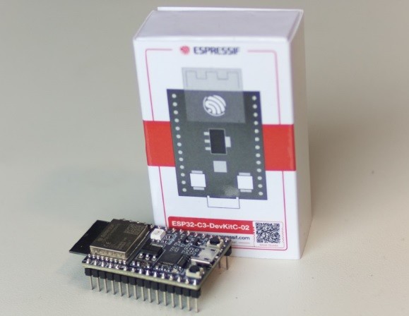
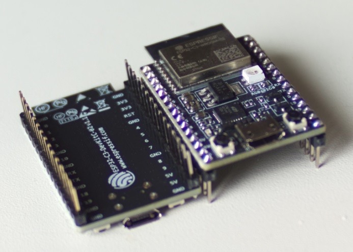
First, we will take a look at the ESP32-C3 and the DevKitC-02 (Figure 1). The ESP32-C3 chip is effectively a successor to the Espressif ESP8266 microchip. Like the ESP8266, it also uses a single core processor which can be clocked at up to 160 MHz and has a 2.4-GHz BGN Wi-Fi communications chip with full TCP/IP stack implementation. But the similarities with the ESP8266 end there. The ESP32-C3 includes many more of the peripherals associated with the ESP32 which is Espressif’s successor to the ESP8266. In addition to Wi-Fi, the ESP32-C3 includes BLE 5.0 and Bluetooth Mesh communications. It also employs the useful GPIO matrix, so that almost any function can be assigned to almost any pin. Figure 2 shows the block diagram of the ESP32-C3, which includes a USB serial/JTAG adapter.
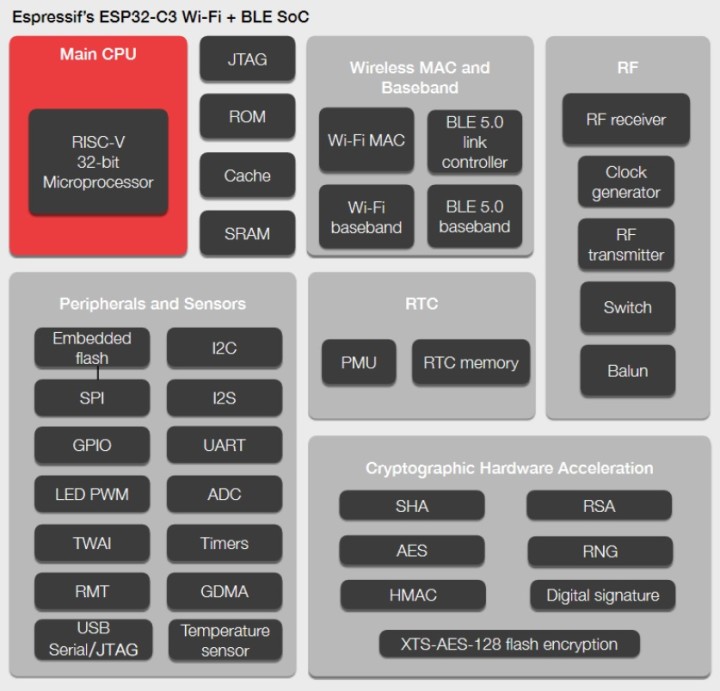
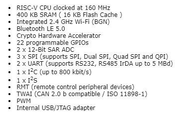
A block diagram of the controller functions is given Figure 2 and shows a clear inheritance from the ESP32 device, with a specification overview in Table 1. With its 384 kB of RAM, the ESP32-C3 offers almost five times more RAM space than the ESP8266 (80 kB). The main component which distinguishes the ESP32-C3 from all other ESP32 or ESP8266 chips is the processor core. While its predecessors use the Tensilica L106 or LX6/LX7 RISC processor, the ESP32-C3 has a RISC-V CPU. This means that compilers and other programs from the RISC-V toolchain can be used with this core. Improvements to these compilers and the corresponding tools will thus benefit users of the ESP32-C3. It is not necessary for the community to set about creating a toolchain as it was when the ESP8266 was first introduced.
The DevKitC-02 board includes a USB-to-serial converter as well as a WS2812-compatible RGB LED. A detailed circuit diagram of the board can be found here. Figure 3 shows both sides of the board.
A Different Take on Blinky
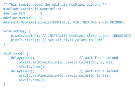
The WS2812-compatible RGB LED installed on the board is controlled using a serial communication protocol so that we can’t get away by just setting an I/O pin to turn the LED on. Fortunately, the Adafruit NeoPixel library contains routines that work with this type of LED. If it is not already installed, you can add it to your Arduino IDE in the normal way. The code in Listing 1 makes the RGB LED flash red. You don’t need to make any special tweaks to the code for it to run on the ESP32-C3. Uploading the code is just as easy as it is with an ESP32. Thanks to the I/O matrix, WS2812 LEDs can also be used with other pins.
Read the Chip Type and Version
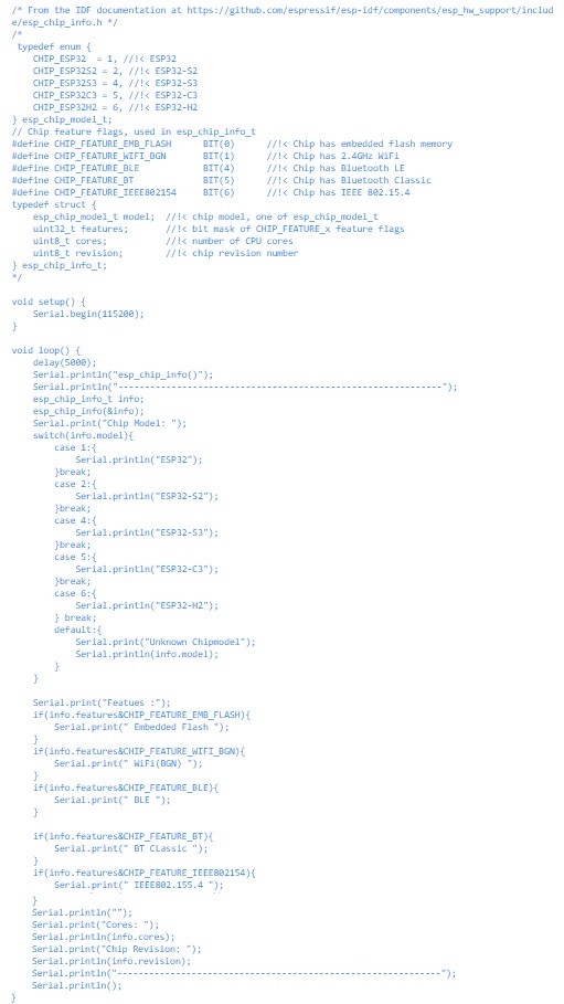
With ESP32 chips, it is possible to read out information stored on-chip showing its basic properties. Listing 2 shows this information read out via the serial interface running at 115200 baud (communication at 9600 baud, with chip revision 2 using the built-in USB-to-serial converter outputs garbled characters). Here you will be able to read which version of the chip is fitted to your ESP32-C3 kit. When you see the list of known bugs associated with revision 2, you will be glad when you can confirm the chip version fitted is not affected.
Porting ESP32 Projects
Some of the most useful features of the ESP32-C3 are its built-in Wi-Fi and BLE communication capabilities. Together with SPIFFS or the LittleFS file system to manage web pages and other data on the ESP32, it makes the platform ideal for a wide range of Wi-Fi applications. Those working with an older 1.X version of the Arduino IDE will need to install a patched plugin for uploading files to the ESP32 file system. The original version by me-no-dev does not work with the ESP32-C3.
As an example, we have used the code which builds an ESP32 Mini-NTP server. This can provide the time of day via NTP in its own network and is written for the Arduino-Framework. After a few tweaks to the pin assignments, the code can be compiled without problems and uploaded to the ESP32-C3. This basic example shows that a lot of existing code and knowledge from the ESP32 will be directly portable to the ESP32-C3, so even newbies to RISC-V environments shouldn’t find the transition too daunting. Most of the existing ESP32 examples will also run on the ESP32-C3, and since FreeRTOS is working in the background here too, you can make use of all the advantages and disadvantages that it brings, as with an ESP32.
Since the ESP32-C3 is currently only supported in a developer branch of the ESP32 chips in the Arduino framework, not all IDEs fully support the chip yet. As the framework matures, we can expect the support level to improve.
ESP32-C3: A Single-Core Solution
The ESP32-C3 is a single-core, cost-effective alternative to the ESP8266 and has many of the peripherals found on the ESP32. The integrated USB/serial and JTAG adapter makes it easy to exchange files and data via USB. You can even start debugging code (as long as nothing unforeseen occurs in revision 3 of the chip).
Thanks to the Arduino framework, existing code can be reused with the ESP32-C3 and the generous amount of RAM and Flash allows larger projects to be considered. Looking to the future, we are sure to see a whole slew of third-party ESP32-C3 boards begin to appear via European outlets, it will be interesting to see what new features these boards will offer. Anyone with an ESP32-DevKitC-02 at home will be in a good position to begin writing and testing code now for this environment. Listings of the Arduino sketches used here can be found on our GitHub page.
Discussion (2 comments)