[Partner Content] By reducing the hardware-in-the-loop test to the microcontroller with the complete software, a complete automation of the test setup can be achieved. Thanks to the use of Continuous Integration, the response times for test execution are in the range of minutes instead of days, weeks or even months.
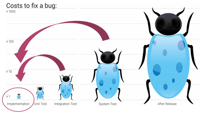
Any small change to an embedded system can have the most malicious effects. Moreover, if you find and fix the problems too late, the fix is very expensive. Therefore, it should be possible to test every change to an embedded system within minutes. This is the only way to ensure that you can detect and fix the problems quickly.
For pure software projects, complete automation of the tests via Continuous Integration (CI) helps. Here, every code change automatically triggers the build and test of the complete software. This allows a full regression test to detect bugs in existing and new code within minutes. Can this also work for embedded systems?
Continuous-Integration for test automation
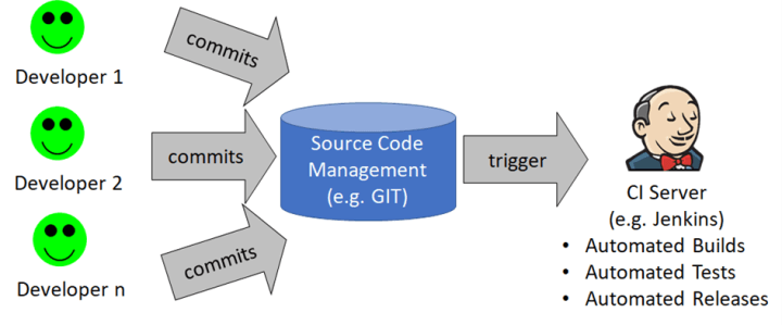
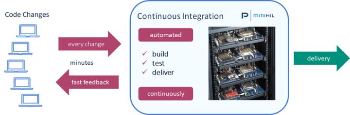
First, let's look at how Continuous Integration works.
1. Each developer updates his software changes by committing to a central source code management system, e.g., GIT.
2. Each commit notifies the Continuous Integration Server application (CI server).
3. The CI server checks out the change just made and completely rebuilds the software project, including the tests.
4. Now all tests are automatically executed for the new software version.
a. If a test fails, only the developer who made the last change is notified - e.g., by email.
b. If all tests run without problems, nobody is notified. But the test results will be logged.
5. In many cases a complete release with documentation and release notes is built. This always ensures that the project is ready for automated delivery at any time.
What is different about embedded systems?
The goal should be to run the tests as soon as possible after each software change. For unit tests, which are usually pure software tests, this is easy. But how can this be achieved for system or integration tests for embedded systems?
Hardware-in-the-loop tests (HIL tests) or manual system tests required for this are often difficult to automate.
Real hardware parts in the test setup prevent automation and repeatability.
Often only the "happy path" can be tested, but not failure behavior.
The test bench is often too expensive to be available for automation for every project at every time.
The problem using the example of an oil pump?
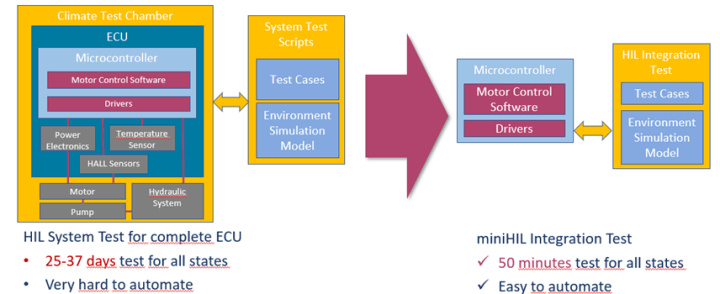
Let's look at an example from a real project. It is a system test for a safety-relevant oil pump. The goal of the test setup: test the temperature shutdown for all relevant system states. The previous setup: The complete system runs in a large climate chamber.
The disadvantages:
Due to the inertia of the climatic chamber, a complete test sequence would take about 30 days. This makes the test practically worthless for software tests in early project phases.
Due to the complex system design, the tests can only be partially automated.
Only the temperature error can be tested. For other fault situations, the motor, the pump or the hydraulic system must be manipulated manually.
The expensive resource climatic chamber is often not available for other important and frequent system tests.
The new setup: We test only the microcontroller, the drivers and the application software and simulate the complete environment. The test is done as a black-box test via the signals on the pins of the microcontroller.
The advantages:
You test what changes most often: the software
One can test not only the temperature shutdown, but also all other potential error situations.
Beside the good case (Happy Path) also all bad cases (Unhappy Path) can be tested by simulation and error injection.
The test execution can be fully automated.
Complete regression tests are performed for every code change.
Execution takes only 50 minutes instead of 30 days.
The hardware setup is significantly cheaper and smaller.
The hardware test setup
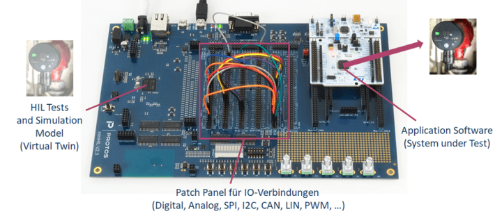
Instead of the complete system, only the microcontroller with the complete unchanged software is tested.
The pins and thus the required signals of the system under test (SUT, right side) are connected to the test system (left side). On the test system runs the environment simulation (motor simulation, hydraulic simulation, temperature simulation, ...) and the automated test cases.
Due to the complete environment simulation, the SUT can be set to any required state and thus the tests can be completely automated. If you have more than one project, or if several developers are working on one project, it is recommended to set up the SUT in a 19 inch cabinet. The example shows 8 different projects in a waist-high cabinet. These are connected to the CI server via USB hub.
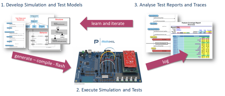
The software development environment
To be able to create environment simulations and test cases as efficiently as possible, we use a model-driven approach. The software structure of the test system and the environment simulations are developed using the ROOM language and the open source tool eTrice. The test cases are also developed model-driven with the language CeGe (Case Generator). C-code is generated from the models, compiled, and transferred to the test system. The results logged during test execution are transformed into various diagrams and standard formats. This makes it easier for developers, project managers and reviewers to interpret the results, learn and start the next iteration in the development process.
Summary
By reducing the hardware-in-the-loop test to the microcontroller with the complete software, a complete automation of the test setup can be achieved. Thanks to the use of Continuous Integration, the response times for test execution are in the range of minutes instead of days, weeks or even months. Developers can thus eliminate errors that occur extremely quickly and without dependencies on other changes. This is an important prerequisite for fast, iterative project development.

Discussion (0 comments)