When working with radio-frequency (RF) signals, it can be useful to have a simple method for incrementally adjusting signal levels. Check out this RF step attenuator design from 2017.
When working with radio-frequency (RF) signals, it can be useful to have a simple method for incrementally adjusting signal levels. For instance, you may need to lower the output of an RF generator beyond its built-in control limits. Attenuators find various applications in adjusting and repairing receivers and other radio equipment. Despite their professional-grade counterparts being expensive, attenuators don't necessitate costly electronics, making a DIY approach a viable option. Take a look at this RF step attenuator design from 2017.
Subscribe
Tag alert: Subscribe to the tag circuit and you will receive an e-mail as soon as a new item about it is published on our website!
RF Attenuator Circuit
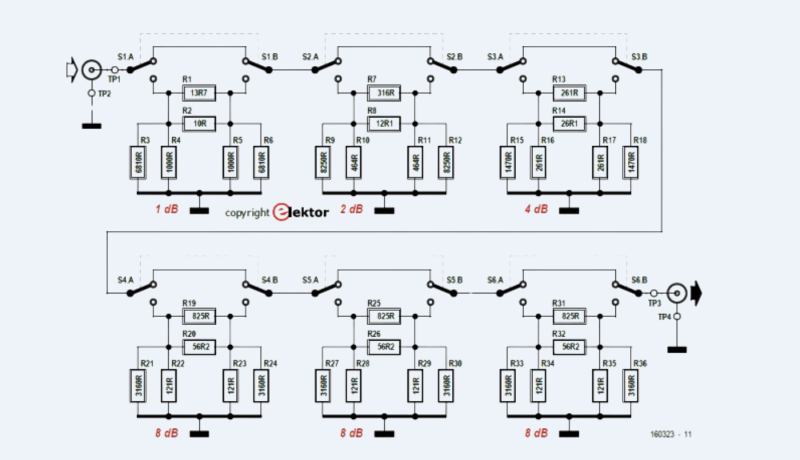
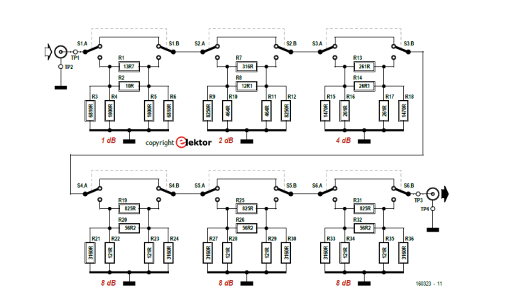
Refer to the circuit, which includes six cascaded pi-type attenuator stages, each of which can be optionally bypassed using a double-pole switch. The board fits neatly into a cast aluminum enclosure.
Complete circuit of the six-stage attenuator.
The author explains: "A point to note is that each resistor in each pi network has been replaced by a parallel combination of two resistors. This allows the calculated ideal value of each resistor to be realized accurately, despite only using standard E-series values. In total, then, the circuit comprises six switches and (up to) 6 × 3 × 2 = 36 resistors."
Appropriate resistor values are selected to achieve the desired attenuation for each stage, he notes. "In theory any attenuation between 0 dB and ∞ dB can be realized; however in practice the maximum attenuation is limited to about 10 dB, as beyond that parasitic effects in the components, printed circuit board and switches (which are not specially designed for RF applications) come into play. The smallest degree of attenuation used in the circuit is 1 dB, although fractions of a decibel could of course be implemented."
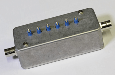
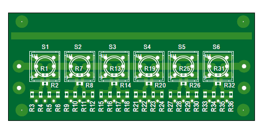
The prototype
The PCB and finished prototype are fairly compact. As the author explains, the attenuator performs well up to approximately 200 MHz.
RF layout techniques were used on the attenuator circuit board.
More on the Project and RF
Alfred Rosenkränzer’s article (160323) the attenuator project appeared in the July/August 2017 edition of Elektor. Elektor Members enjoy ElektorMag, an Elektor Store discount on most products, and full access to Elektor’s online library, which includes this article and many others. Take out a membership today!
Subscribe
Tag alert: Subscribe to the tag RF and you will receive an e-mail as soon as a new item about it is published on our website!
Elektor Magazine has been one of the leading sources of information on electronics for engineers, designers, start-ups and companies for 65 years. Our magazine is powered by an active community of electronics engineers – from students to professionals – who are passionate about designing and sharing innovative ideas.
For them, we publish hundreds of items a year, in formats such as articles, videos, webinars, and other learning formats. Our mission is to share knowledge in every possible way and inspire readers with the latest developments within the electrical engineering sector.
Thank you for your vote!
Leave further comments in the fields below.
Thank you for your vote!
If you wish to leave a comment with your rating, please first use the login below. If not, just close this window.


Discussion (0 comments)