
Small Circuits Revival – Episode 12
on
Reflex Receiver with MOSFETs
idea: Elex Team
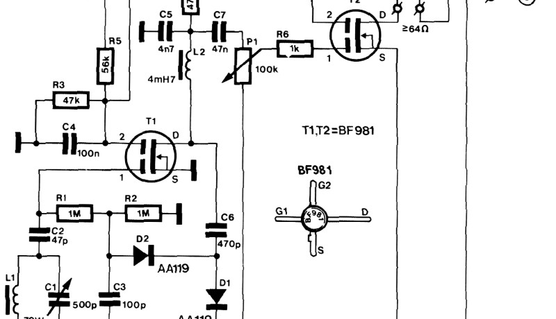
In the previous episode we presented the schematic of a practical reflex receiver – see Figure 1 below. First a brief reminder: in a reflex receiver the received RF signal is amplified before it goes to the detector; this amplifier, however, is used twice and also amplifies the detected (audio) signal.
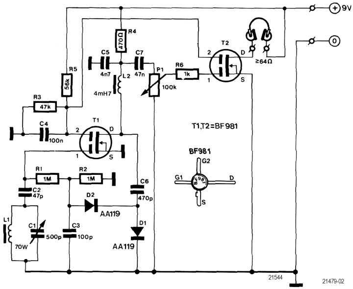
In this schematic we used two dual-gate MOSFETs. T1 forms the heart of he circuit. R3 and R5 provide the DC bias of gate 2 of both FETs; C4 provides the decoupling. C5 decouples the drain of T1.
The tuning is provided by L1 and C1; L1 consists of 70 turns of enamelled copper wire on a ferrite rod and simultaneously serves as the antenna. The tuned signal goes to gate 1 of T1 via C2 . The input impedance of this transistor is so high that it does not damp the tuning circuit.
The RF signal amplified by T1 is blocked by filter inductor L2 and passes through C7 and arrives on detector D1, D2, C3 and R2 – which also functions as a voltage doubler. The rectified signal returns via R1 to gate 1 of T1, where it is amplified and now can pass through L2.
The AF signal (audio signal) is coupled out through C7 and via volume control P1 arrives on transistor T2 which serves as an ‘ordinary’ LF amplifier. This provides sufficient power to allow headphones that don't have very high impedances to be driven.
The entire circuit can be built very compactly using the ‘point-to-point’ or dead bug technique (i.es without a circuit board). And to pre-empt any potential worries: the BF981 is still available on eBay; and the circuit may also work with ‘more modern’ variants (although we have not tried that ourselves) – an opportunity for your own experiments!
Next week we will move on to other things than radio.
Discussion (1 comment)