
Small Circuits Revival (22): Dry Soil Alarm
on

Dry Soil Alarm
idea: Kees van der Geer (Netherlands)
The idea behind this circuit is actually simplicity itself: as the soil around the roots of the plant dries, its (electrical) resistance increases. Measure this resistance in one way or another; and once it becomes too high (and therefore the soil in the pot is too dry) raise the alarm.
This idea is realised in the schematic of Figure 1. The circuit essentially consists of the two comparators in a TLC3702. The first is configured as an oscillator (astable multivibrator); the period is about 2 seconds with the component values as indicated.
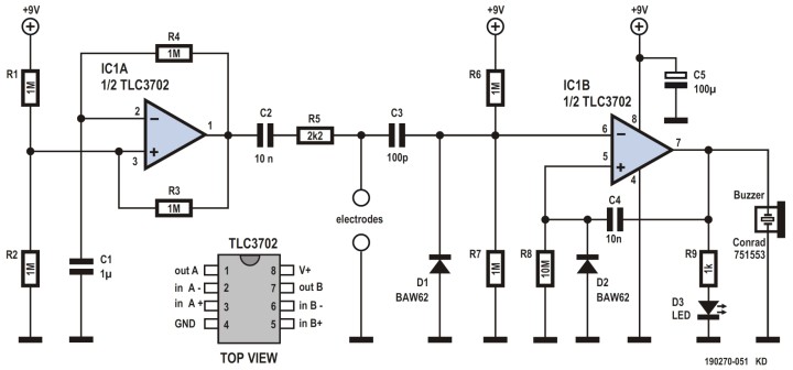
Brief positive- and negative-going pulses arrive via capacitors C2 and C3 at the inverting input of the second comparator, which is configured as a ‘one-shot’ (C2 and R5 plus both the electrodes effectively function as a differentiator).
Depending on whether the soil is more or less moist, a larger or smaller amount of the pulse is diverted via the pair of electrodes to ground. Or expressed differently: as the soil in the pot dries out, an increasingly less-attenuated pulse arrives at the second comparator.
The positive-going pulses have no further effect, but because of the alternating positive- and negative-going pulses, no corrosion of the electrodes will occur – a hidden advantage of this design.
When the negative-going pulse at the inverting input of the second comparator becomes large enough, the one-shot will be triggered and the LED will light up for about 100 ms; at the same time the buzzer will generate an urgent beep. This will continue until the thirsty plant has been watered.
In itself this circuit is not really amazing; the nice feature, however, is that it is extremely energy efficient. Even when the LED and buzzer are continually activated every couple of seconds, the battery (a 9-V PP3 block) will last for months. This is a benefit of the IC used here in combination with the extremely high resistance values.
Discussion (0 comments)