
Small Circuits Revival (30): Pocket synthesizer (2)
on
idea: Elex Team
Pocket synthesizer (2)
We have drawn the complete schematic below.
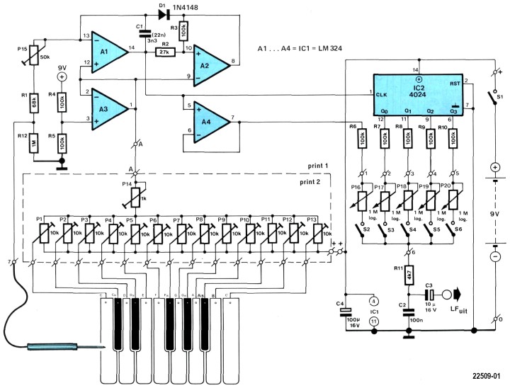
The VCO is built using opamps A1 and A2 plus surrounding components. IC2 (an old CMOS-acquaintance for the not-so-young electronics enthusiasts among us) forms the divider.
A3 is actually a buffer. Half of the power supply voltage magnitude is applied via R4 and R5 to its non-inverting input; at its output is a buffered version thereof (i.e. capable of heavier loading), which functions as an artificial ground. This way we avoid the need for a symmetrical (positive and negative) power supply.
The ‘clavier’ (keyboard) with the stylus is used to operate the different (metal!) keys can be seen at bottom left. The synthesizer is tuned with the row of trimpots. The mixing stage can be seen below IC2: The signal of the highest octave is buffered by A4; The repeatedly divided-by-2 signals are supplied by Q0 through Q3 of IC2. These signals are summed to your liking via P16 through P20, and the final result goes via C3 to an amplifier.
A comment about the adjustment (the ‘tuning’): for this you need a well-tuned reference instrument (piano, guitar, recorder). Close S2 (the other switches remain open). Turn P13 to its top setting and P1 to its bottom setting. Turn on the power supply voltage with S1. Now adjust P14 so that the difference between the highest and lowest tone is one octave (fine adjustment with P13, if necessary). Now P15 has the be adjusted such that the lowest tone corresponds to the ‘C’ of the reference instrument. If necessary, you can adjust the value of C1 a little. And finally P2 through P12 are adjusted so that the intermediates tones also sound right, just like the reference instrument.
In closing: if you build this circuit as a toy for young children, then buy a set of ear plugs for yourself first; and if you are going to experiment with this circuit yourself, then buy a set of ear plugs for your neighbours :-))
Discussion (1 comment)